
Machine vision system

A technology of machine vision inspection and parts program, which is applied in general control systems, control/regulation systems, instruments, etc., and can solve problems such as unfavorable movement of platforms under environmental conditions

Active Publication Date: 2013-05-15
MITUTOYO CORP
View PDF8 Cites 10 Cited by
  • Summary
  • Abstract
  • Description
  • Claims
  • Application Information

AI Technical Summary

Problems solved by technology

Also, if the user saves a partially complete part program and later recalls the part program to change or complete the programming, it may not be known if certain types of changes occurred in the intervening period that could adversely affect continuing to edit the part program (e.g. , changes in environmental conditions, unfavorable moving parts of the platform, etc.)

Method used


Image

  • Machine vision system
  • Machine vision system
  • Machine vision system

Examples


Embodiment Construction

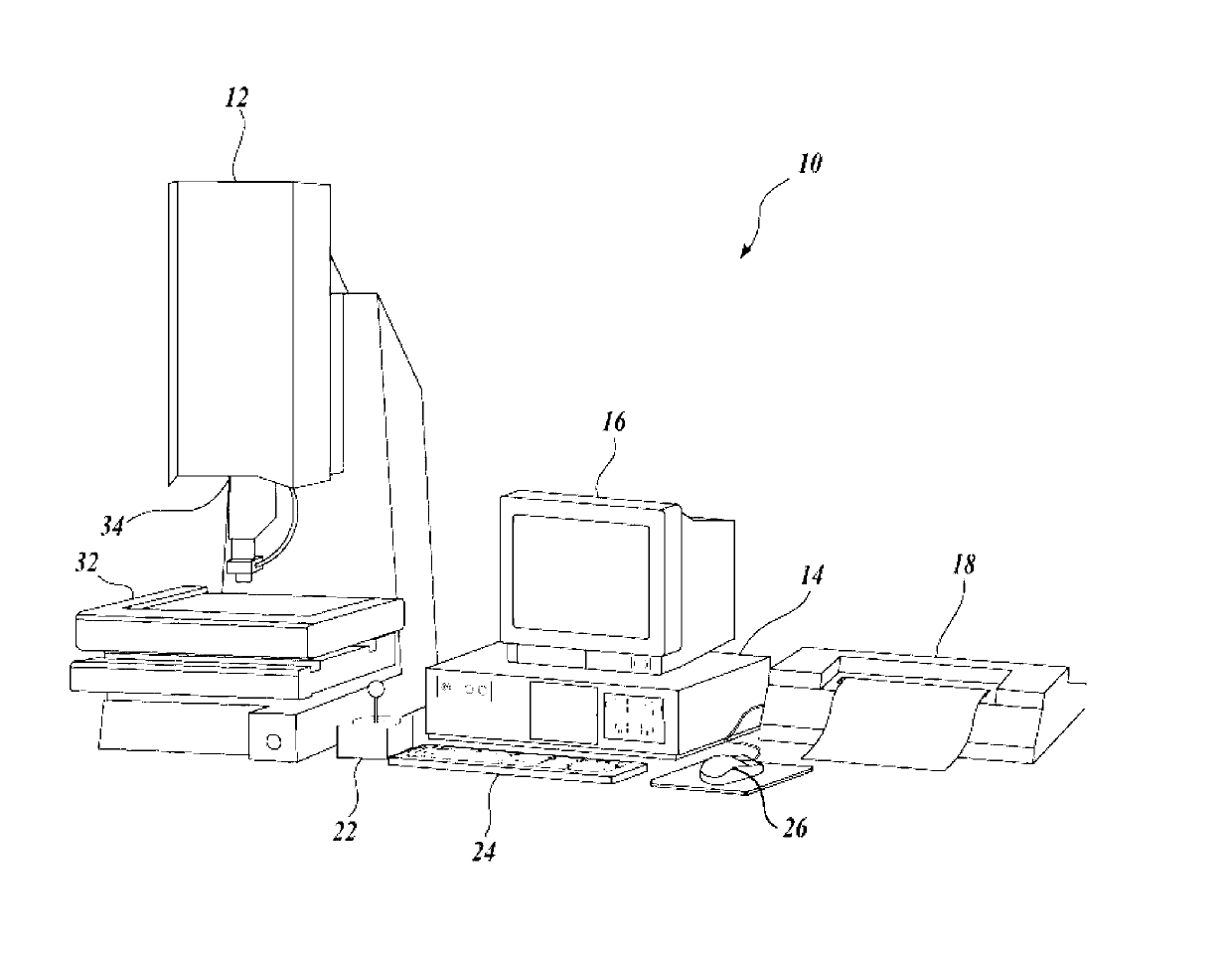
[0042] figure 1 is a block diagram of an exemplary machine vision inspection system 10 that may be used in accordance with the methods described herein. The machine vision inspection system 10 includes a vision measurement machine 12 operably connected to exchange data and control signals with a control computer system 14 . Control computer system 14 is also operably connected to exchange data and control signals with monitor or display 16 , printer 18 , joystick 22 , keyboard 24 and mouse 26 . Monitor or display 16 may display a user interface suitable for controlling and / or programming the operation of machine vision inspection system 10 .

[0043] Vision measurement machine 12 includes a movable workpiece stage 32 and an optical imaging system 34 that may include a zoom lens or interchangeable lenses. Zoom lenses or interchangeable lenses typically provide various magnifications to the image provided by optical imaging system 34 . Machine vision inspection systems 10 are...


PUM


Abstract

A machine vision system program editing environment includes near real time context generation. Rather than requiring execution of all preceding instructions of a part program in order to generate a realistic context for subsequent edits, surrogate data operations using previously saved data replace execution of certain sets of instructions. The surrogate data may be saved during the actual execution of operations that are recorded in a part program. An edit mode of execution substitutes that data as a surrogate for executing the operations that would otherwise generate that data. Significant time savings may be achieved for context generation, such that editing occurs within an operating context which may be repeatedly refreshed for accuracy in near real time. This supports convenient program modification by relatively unskilled users, using the native user interface of the machine vision system, rather than difficult to use text-based or graphical object-based editing environments.

Description

technical field [0001] The present invention relates generally to machine vision inspection systems, and in particular to methods for creating and editing part programs in these systems. Background technique [0002] Precise machine vision inspection systems (or simply "vision systems") can be used to obtain precise dimensional measurements of inspected objects and detect various other object characteristics. Such a system may include a computer, camera and optics, and a precision stage movable in multiple directions to allow the camera to scan features of the workpiece being inspected. One commercially available exemplary prior art system is the QUICK for computer vision systems series and sold by Mitutoyo America Corporation (MAC) of Aurora, Illinois software. For example, QVPAK3D CNC Vision Measuring Machine User's Guide published in January 2003 and QVPAK3D CNC Vision Measuring Machine Operation Guide published in September 1996 generally describe the vision system'...

Claims


Application Information

Patent Timeline
Patent Type & Authority Applications(China)
IPC IPC(8): G06F9/44G01B11/00
CPCG01N21/88G05B19/409G06F8/30G05B2219/35505G05B2219/36143G01N21/8851G05B19/4093G05B2219/37455G05B2219/37208G05B2219/37439G05B2219/36172G06F9/44Y02P90/02Y10S715/964Y10S715/965Y10S715/97
Inventor B.塞勒于大海R.诺思拉普张玉武高田彰
Owner MITUTOYO CORP
Learn More