
Imaging module of projector and projector using the same

A technology of an imaging component and a projection device, which is applied in the field of projection display, can solve the problems of difficulty in ensuring product consistency, low productivity, and great influence on projection effects, and achieves the effects of reducing smearing, high production efficiency, and improving imaging effects.

Inactive Publication Date: 2013-05-15
BUTTERFLY TECH SHENZHEN
View PDF6 Cites 2 Cited by
  • Summary
  • Abstract
  • Description
  • Claims
  • Application Information

AI Technical Summary

Problems solved by technology

During assembly, the DMD is usually fixed on the housing of the projection device by screws, and then the total internal reflection prism is placed in the corresponding position of the housing, and the verticality of the total internal reflection prism and the parallelism with the DMD are artificially adjusted. After that, the total internal reflection prism is fixed by dispensing glue. Since the total internal reflection prism and DMD are adjusted separately by humans, the productivity is low, and the projection effect is greatly affected by human factors, and it is difficult to ensure product consistency.

Method used


Image

  • Imaging module of projector and projector using the same
  • Imaging module of projector and projector using the same
  • Imaging module of projector and projector using the same

Examples


Embodiment Construction

[0016] The present invention will be further described below in conjunction with the accompanying drawings and specific embodiments.

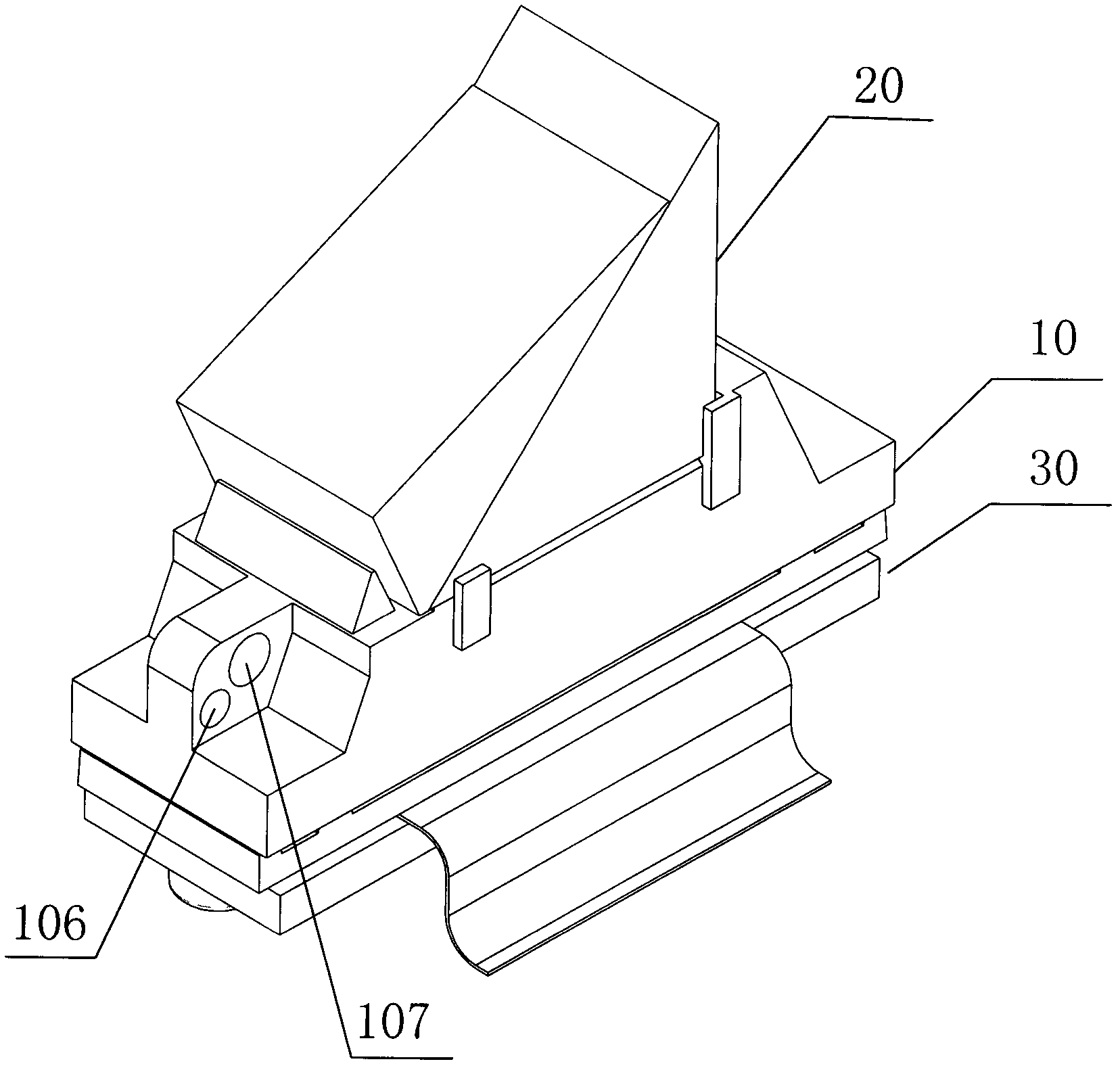
[0017] figure 1 Shown is a schematic diagram of the three-dimensional structure of the imaging assembly of the projection device of the present invention, while referring to figure 2 ,for figure 1 exploded view of the . The imaging component of the projection device includes a prism, a light modulator and a hollow link bracket 10 . Wherein, the prism and the light modulator are relatively parallel connected to the front and back of the link bracket 10 to form an integration. In other words, the prism and the light modulator are integrated through the link bracket 10 .

[0018] In the embodiment of the present invention, the prism is a total internal reflection prism 20, and the light modulator is a DMD30 (that is, an imaging component of a DLP projection device). Wherein, the prism is bonded to the front side of the linking bracket 10 by ...


PUM


Abstract

The invention discloses an imaging module of a projector. The imaging module of the projector comprises a prism, a light modulator and a hollow connecting support frame, wherein the prism and the light modulator are connected on the front face and the back of the connecting support frame in a relatively parallel mode to form into a whole. The imaging module integrates the prism and the light modulator into a whole through the connecting support frame so as to ensure that relative positions of the prism and the light modulator are not changed, parallelism of the prism and the light modulator can be effectively ensured, and consistency of optical performance is ensured. In addition, due to the integral design, maintenance and protection of the modulator are convenient, adjustment is reduced at the same time, assembling efficiency is improved, tool equipment is simplified, and production efficiency is further improved. In addition, the invention further provides the projector using the imaging module.

Description

technical field [0001] The invention relates to projection display technology, in particular to an imaging component of a projection device and a projection device using the same. Background technique [0002] In recent years, projection technology has been widely used in audio-visual teaching, office, business, advertising and entertainment. One of the projection technologies is digital light processing (Digital Light Processing, DLP) technology, which requires digital processing of image signals before projecting light. It is based on the digital micromirror device (Digital Micromirror Device, DMD) developed by Texas Instruments (TI) to complete the technology of visual digital information display. Specifically, the DLP projection technology uses a digital micromirror chip (DMD) as the main key processing element to realize the digital optical processing process. [0003] In a commonly used DLP projection device, a traditional total internal reflection (Total Internal Re...

Claims


Application Information

Patent Timeline
IPC IPC(8): G03B21/14G02B5/04G02B5/30
Inventor 杨勇黄彦程晓辉马红虎
Owner BUTTERFLY TECH SHENZHEN
Learn More