Etching method of blazing concave surface holographic grating subarea reaction ion beams
A concave grating and holographic grating technology, applied in the field of spectroscopy, can solve the problems of different blaze angles and affect the diffraction efficiency of blazed concave gratings, and achieve the effects of improving diffraction efficiency, high blaze angle consistency, and easy implementation
- Summary
- Abstract
- Description
- Claims
- Application Information
AI Technical Summary
Problems solved by technology
Method used
Image
Examples
specific Embodiment approach 1
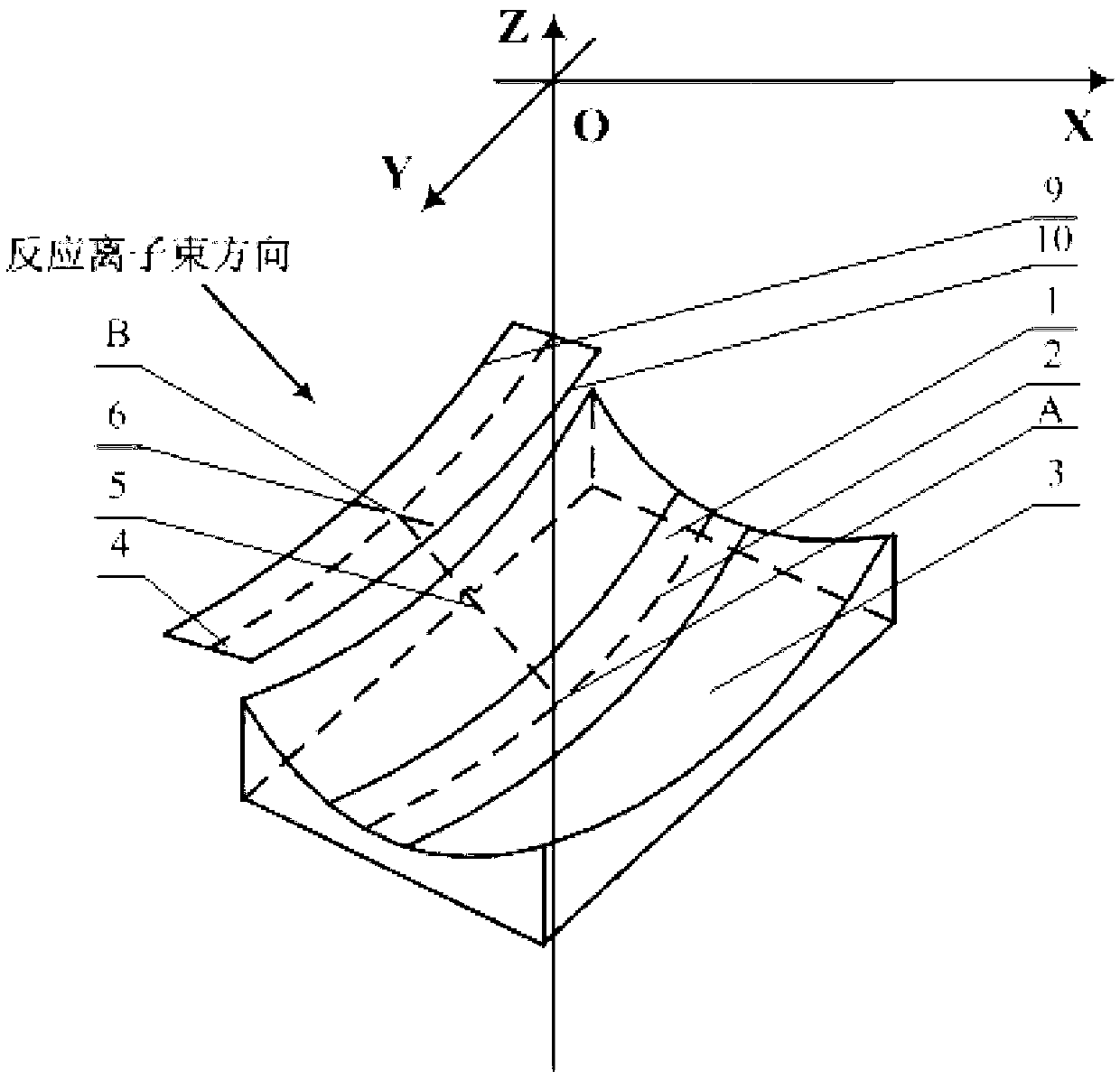
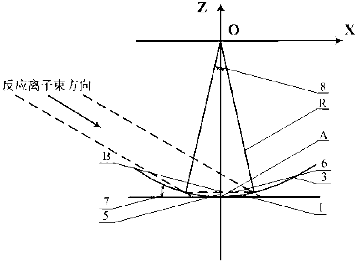
[0017] Specific implementation mode 1. Combination figure 1 and figure 2 Describe this embodiment, the blazed concave holographic grating partitioned reactive ion beam etching method, the method is realized by the following steps:
[0018] Step 1, placing the concave grating mask substrate 3; place the concave grating mask substrate 3 with a sinusoidal or rectangular groove shape on a rotary table, the center of rotation of the table is O, and the coordinate system is XYZ , can make a rotary motion around the Y axis, the center of the ball is on the rotary axis Y of the rotary table, that is, the coordinate origin O in the figure; the plane where the grating line 2 at the apex A of the concave grating mask substrate 3 passes through the rotary axis Y, The planes where the rest of the engraved lines are located are parallel to the axis of rotation Y.
[0019] Step 2, select the ion beam incident angle; figure 2 As shown, if the spherical radius of the concave grating mask ...
specific Embodiment approach 2
[0025] Specific embodiment two, combine Figure 1 to Figure 5 This implementation mode is described. This implementation mode is an example of the blazed concave holographic grating partitioned reactive ion beam etching method described in the first specific implementation mode: the specific process is as follows:
[0026] Step 1. Placement of the concave grating mask substrate 3; place the concave grating mask substrate 3 with a rectangular groove shape on a rotary table, the center of rotation of the table is O, and the coordinate system is XYZ, which can be rotated around The Y axis makes a rotary motion, and the center of the ball is on the rotary axis Y of the rotary table, that is, the coordinate origin O in the figure; the plane where the grating line 2 at the vertex A of the concave grating mask passes through the rotary axis Y, and the planes where the other lines are located are parallel to The axis of rotation Y, where the groove shape of the concave holographic gra...
PUM
| Property | Measurement | Unit |
|---|---|---|
| Width | aaaaa | aaaaa |
| Length | aaaaa | aaaaa |
Abstract
Description
Claims
Application Information
 - Generate Ideas
- Intellectual Property
- Life Sciences
- Materials
- Tech Scout
- Unparalleled Data Quality
- Higher Quality Content
- 60% Fewer Hallucinations
Browse by: Latest US Patents, China's latest patents, Technical Efficacy Thesaurus, Application Domain, Technology Topic, Popular Technical Reports.
© 2025 PatSnap. All rights reserved.Legal|Privacy policy|Modern Slavery Act Transparency Statement|Sitemap|About US| Contact US: help@patsnap.com


