
Series resonance voltage-withstanding partial-discharge test method utilizing frequency modulation phase shift

A technology of series resonance withstand voltage and test method, applied in the direction of testing dielectric strength, etc., can solve the problems of large volume, low efficiency and high noise

Active Publication Date: 2015-07-08
丁一舟
View PDF4 Cites 0 Cited by
  • Summary
  • Abstract
  • Description
  • Claims
  • Application Information

AI Technical Summary

Problems solved by technology

This power supply basically has no interference, but it has low efficiency, high noise, large volume and poor reliability; while the previous partial discharge test systems using rectangular wave or square wave frequency conversion power supply have high power efficiency, small volume and reliable operation, but The burrs generated when the switch tube is turned on and off will affect the partial discharge measurement

Method used


Image

  • Series resonance voltage-withstanding partial-discharge test method utilizing frequency modulation phase shift
  • Series resonance voltage-withstanding partial-discharge test method utilizing frequency modulation phase shift
  • Series resonance voltage-withstanding partial-discharge test method utilizing frequency modulation phase shift

Examples


Embodiment Construction

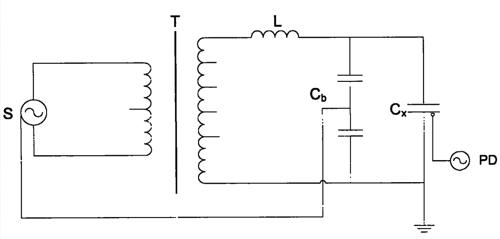
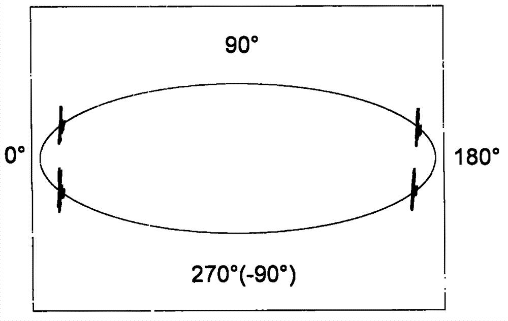
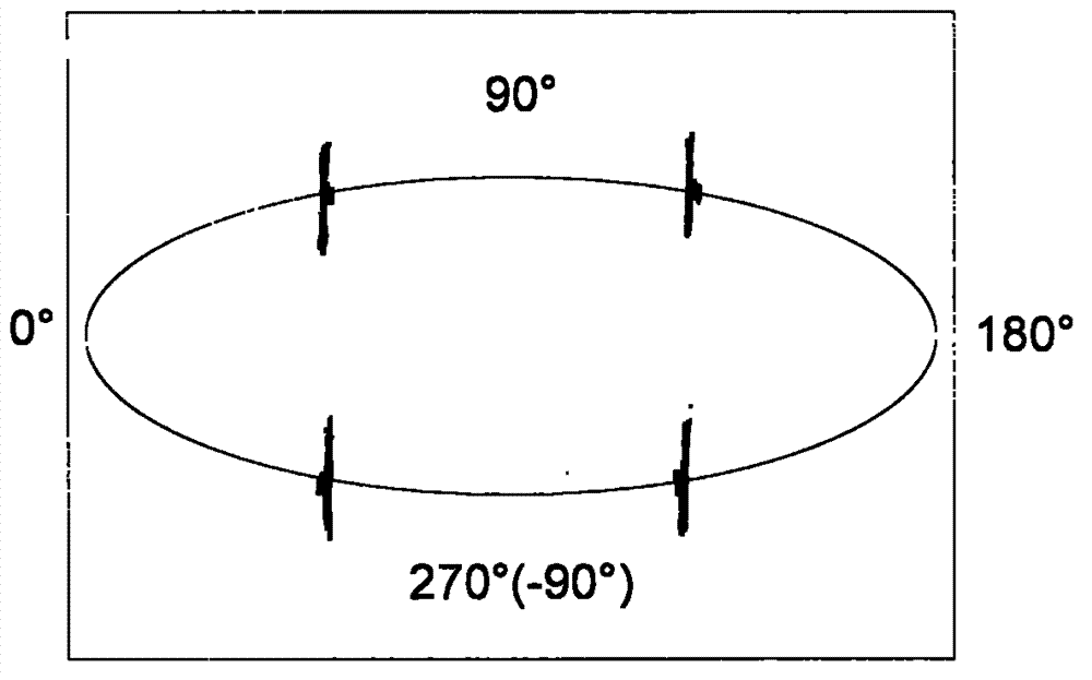
[0006] Example 1 see attached figure 1 As shown in the frequency modulation series resonant voltage withstand partial discharge test system using a rectangular wave frequency conversion power supply, this method is used as follows: first use a small pulse width (such as 2%) to excite the frequency sweep tuning of the voltage to make the system reach a resonance state, and then increase the pulse width Boost. With the increase of the pulse width, the four glitches formed on the time base of the partial discharge instrument when the switching tube of the variable frequency power supply is turned on and off (see the attached figure 2 ) will move closer to ±90° (see attached image 3 ). If the final resonant voltage reaches the set value of the test voltage, the 4 burrs close together and become 2 at ±90° (see attached Figure 4 ), you can operate the partial discharge instrument to read the partial discharge amount of the test product by opening the window in the first and th...


PUM


Abstract

The invention discloses a series resonance voltage-withstanding partial-discharge test method utilizing frequency modulation phase shift, and relates to alternating current voltage-withstanding and partial-discharge test of electrical equipment. According to the series resonance voltage-withstanding partial-discharge test method utilizing frequency modulation phase shift, a frequency modulation series resonance voltage-withstanding partial-discharge test system composed of a rectangular wave variable-frequency power source, a resonant electric reactor, a partial-discharge instrument and the like is utilized, excitation voltage frequency is down-regulated when a resonance voltage reaches a set value of the test voltage, the system deviates from the resonant state and produces phase shift, four burrs (namely interference signals) formed on a time base of the partial-discharge instrument when a variable-frequency power source switching tube is switched on and switched off are moved to second and fourth quadrants rightwards from positions distributed on two edges of + / - 90 degrees, the excitation voltage pulse width is increased to enable the resonance voltage to reach the set value of the test voltage again, and then windows can be opened at first and third quadrants for partial discharge test of tested products. By means of the series resonance voltage-withstanding partial-discharge test method, interference on the partial-discharge test, caused by variable-frequency power source switching pulses, is avoided, the fact that people doubt whether windowing or blanking eliminates the partial discharge of the tested products is avoided, and therefore the reliable and high-efficiency rectangular wave variable-frequency power source is used for the voltage-withstanding partial-discharge test of various kinds of electrical equipment.

Description

technical field [0001] The invention relates to the electric insulation performance test of the electric equipment, especially the AC withstand voltage and partial discharge test of the electric equipment. Background technique [0002] Before the power line is put into operation or after the overhaul, the insulation state of the power components or equipment must be inspected and evaluated. Among these tests, AC withstand voltage is a basic and important test, while partial discharge measurement is a more advanced test method developed in recent years with the functions of early diagnosis of insulation state and prediction of development trend. Both tests require the application of AC high voltage to the test object. [0003] There are three basic methods of applying AC high voltage: external application method, induction method and resonance method. The resonance method is to use a reactor and the tested product (equivalent to a capacitor) to form an LC circuit, and make ...

Claims


Application Information

Patent Timeline
Patent Type & Authority Patents(China)
IPC IPC(8): G01R31/12
Inventor 丁一舟
Owner 丁一舟
Learn More