A high spatial resolution confocal Raman spectroscopy detection method and device
A high spatial resolution and spectral detection technology, applied in the field of high spatial resolution confocal Raman spectral detection, can solve the problem that the spatial resolution is difficult to improve, and achieve the effect of controllable size and improved sensitivity
Active Publication Date: 2014-10-15
BEIJING INSTITUTE OF TECHNOLOGYGY
View PDF4 Cites 0 Cited by
- Summary
- Abstract
- Description
- Claims
- Application Information
AI Technical Summary
Problems solved by technology
[0007] The purpose of the present invention is to propose a confocal Raman spectroscopy detection method and device with high spatial resolution in order to overcome the deficiency that the spatial resolution of the existing confocal Raman spectroscopy detection technology is difficult to improve
Method used
View moreImage
Smart ImageViewing Examples
Examples
Embodiment
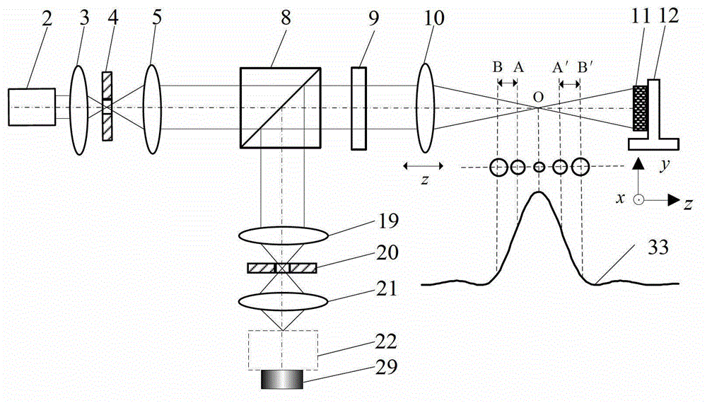
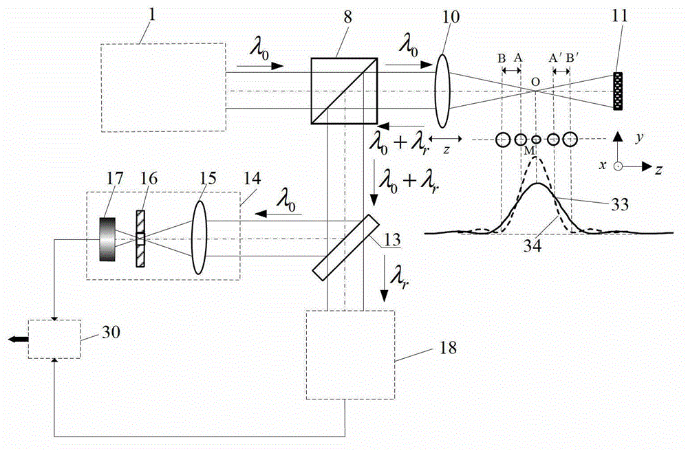
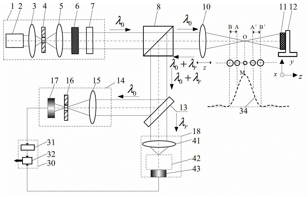
[0052] In this embodiment, the first beam splitting system 8 is a polarization maintaining beam splitting prism, the second beam splitting system 35 is a polarization maintaining beam splitting prism, the third beam splitting system 38 is a broadband beam splitting prism, and the dichroic beam splitting system 13 is a Notch filter.
Login to View More PUM
 Abstract
The invention belongs to the technical field of optical microscopic imaging and spectral measurement, and relates to a method and a device for confocal Raman spectrum detection with high spatial discrimination. According to the method and the device, confocal technique is integrated into the spectrum detection; nondestructive separation is carried out on Rayleigh scattering light and Raman scattering light by using of a dichroic beam splitting system (13); by using the characteristic that the maximum value of a confocal curve (34) corresponds to a focal position accurately, spectral information exciting a light spot focal position is accurately acquired through maximizing; and the spectrum detection with the high spatial discrimination is achieved, and the method and the device which are capable of achieving the sample microcell spectrum detection with the high spatial discrimination are formed. The method and the device for the confocal Raman spectrum detection with the high spatial discrimination have the advantages of being accurate in positioning, high in spatial discrimination, high in spectrum detection sensitivity and the like, and has broad application prospect in the fields of biomedicine, court evidence collection and the like.
Description
technical field [0001] The invention belongs to the technical field of optical microscopic imaging and spectral measurement, and relates to a high spatial resolution confocal Raman spectral detection method and device, which can be used for three-dimensional shape reconstruction and micro-region spectral detection of various samples. technical background [0002] Laser confocal Raman spectroscopy testing technology is a new technology that combines microscopic analysis technology and Raman spectroscopy analysis technology. It focuses the incident laser light on the sample through the microscope, so that it can obtain The molecular structure and so on of the illuminated sample micro-area are called molecular probes. It can not only observe the Raman spectrum signals of different micro-regions in the same layer of the sample, but also observe the Raman signals of different layers in the sample at different depths, and perform tomographic scanning on the tested sample, so as to...
Claims
Login to View More Application Information
Patent Timeline
 Patent Type & Authority Patents(China)
IPC IPC(8): G01J3/44
Inventor 赵维谦崔晗邱丽荣王允
Owner BEIJING INSTITUTE OF TECHNOLOGYGY
Features
- R&D
- Intellectual Property
- Life Sciences
- Materials
- Tech Scout
- Unparalleled Data Quality
- Higher Quality Content
- 60% Fewer Hallucinations
Learn More Browse by: Latest US Patents, China's latest patents, Technical Efficacy Thesaurus, Application Domain, Technology Topic, Popular Technical Reports.
© 2025 PatSnap. All rights reserved.Legal|Privacy policy|Modern Slavery Act Transparency Statement|Sitemap|About US| Contact US: help@patsnap.com


