
Pitch-varying design method of inducer with long and short blades

A technology of long and short blades and design methods, applied in mechanical equipment, non-variable pumps, components of pumping devices for elastic fluids, etc., can solve the problem of reducing the efficiency of the inducer and anti-cavitation performance, shedding and boundary Layer separation and other issues, to improve efficiency and anti-cavitation performance, to avoid the effect of boundary layer separation

Inactive Publication Date: 2013-05-15
JIANGSU UNIV
View PDF4 Cites 9 Cited by
  • Summary
  • Abstract
  • Description
  • Claims
  • Application Information

AI Technical Summary

Problems solved by technology

When the variable pitch inducer is used, the edge distance at the outlet of adjacent blades becomes larger, which will easily cause shedding and boundary layer separation near the outlet of the inducer blades, seriously reducing the efficiency and anti-cavitation performance of the inducer

Method used


Image

  • Pitch-varying design method of inducer with long and short blades
  • Pitch-varying design method of inducer with long and short blades
  • Pitch-varying design method of inducer with long and short blades

Examples


Embodiment Construction

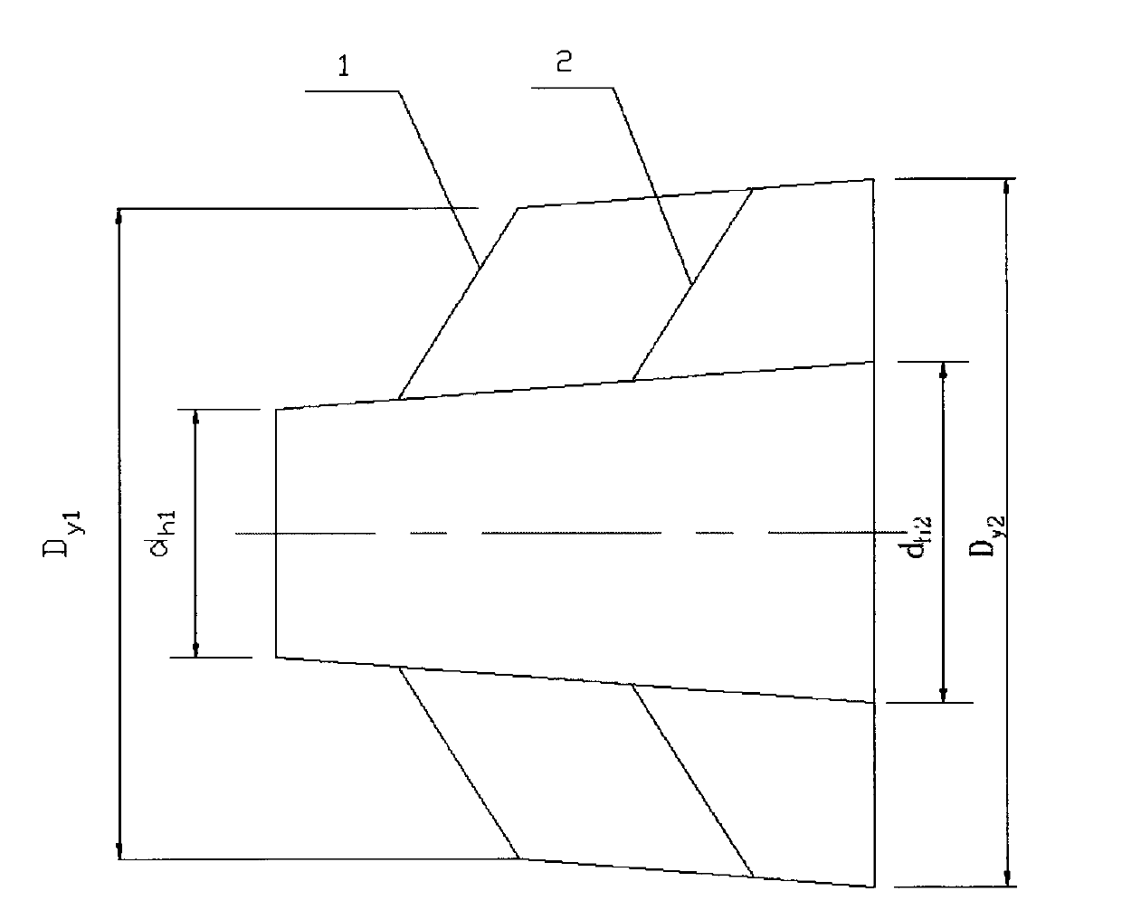
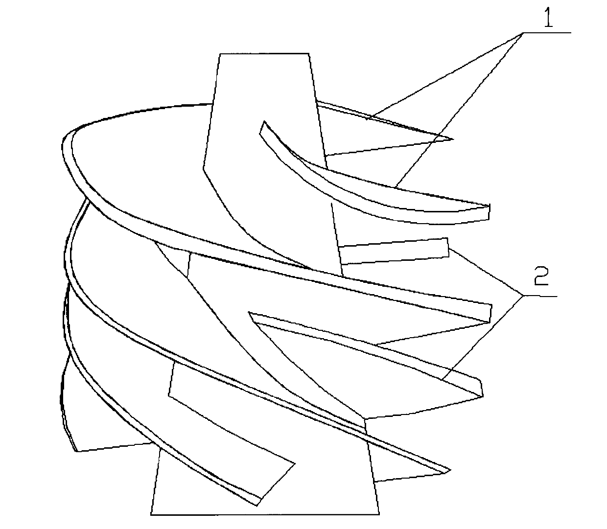
[0049] figure 1 with figure 2 Together determine the shape of this embodiment inducer. It has a tapered hub like most tapered inducers. The blades of the inducer are divided into two types: long blades (1) and short blades (2). The long and short blades are arranged alternately. There are two long and short blades on the inducer. The short blades extend from the middle of the inducer to the exit. Its main purpose is to avoid shedding and boundary layer separation near the outlet of the inducer blades, improve the outlet flow field, and improve the efficiency and anti-cavitation performance of the inducer.


PUM


Abstract

The invention relates to a pitch-varying design method of an inducer with long and short blades. On the basis of the design of a conical pitch-varying inducer, the long and short blades of the inducer are designed to be alternatively arranged, and the outlets of the long and short blades are positioned on one same radial surface. By virtue of the design method, flow separation and boundary layer separation near the outlets of the blades of the inducer are avoided, an outlet flow field is improved, and the efficiency and the cavitation resistance of the inducer are improved.

Description

Technical field: [0001] The invention relates to a design method of an inducer, in particular to a variable pitch design method of an inducer with long and short blades, which is used for improving the flow field at the outlet of the inducer and improving its anti-cavitation performance. Background technique: [0002] At present, the inducer has been widely used to improve the anti-cavitation performance of the pump. The inducer belongs to the axial flow impeller, which has the geometric characteristics and cavitation characteristics of the axial flow impeller. The air bubbles generated on the outer edge of the inducer move forward along the axial direction due to the centrifugal force of the liquid on the hub side. , outward pressure, so that the air bubbles are pressure-controlled on the local part of the outer edge and condense in the induction wheel, so it is not easy to cause blockage of the entire flow channel. Its external characteristic is that the performance decli...

Claims


Application Information

Patent Timeline
Patent Type & Authority Applications(China)
IPC IPC(8): F04D29/18F04D29/66
Inventor 朱荣生龙云付强王秀礼
Owner JIANGSU UNIV
Learn More