Belt separating unit

A separation device and belt technology, used in transportation and packaging, conveyors, conveyor objects, etc., can solve problems such as low efficiency, scratches, time-consuming and labor-intensive

Inactive Publication Date: 2013-05-15
CHONGQING JUKANG BUILDING MATERIAL
View PDF0 Cites 11 Cited by
  • Summary
  • Abstract
  • Description
  • Claims
  • Application Information

AI Technical Summary

Problems solved by technology

[0003] The existing belt separation devices generally use manipulators and claws, and some even use manual screening and separation, which is time-consuming, laborious and inefficient.
For the separation device using manipulators and claws, although the workpieces can be arranged and separated, the cost of the separation device is high and the efficiency is low. At the same time, the above separation equipment often scratches the outer surface of the workpiece, causing some high-precision workpieces to be scrapped.

Method used


Image

  • Belt separating unit

Examples


Embodiment Construction

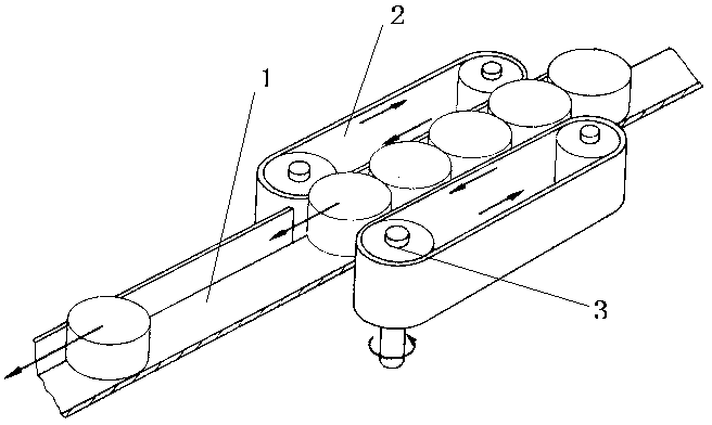
[0010] Such as figure 1 Shown: The belt separation device includes a workpiece storage part and a separation part. The workpiece storage part is a chute 1 arranged horizontally; the separation part includes two endless belts 2 which are symmetrical to the chute 1 and arranged close to the chute 1. The belt 2 consists of Belt pulley 3 drives, and the motion direction of two belts 2 is the same.

[0011] In this embodiment, the workpiece storage part is a horizontally arranged chute 1, and the workpiece flows in from one end of the chute 1, and the workpiece is pushed to the other end of the chute 1 by two moving belts 2 on the side of the chute 1, and enters the lower end of the chute 1. One-step machining equipment; at the same time, the belt 2 is driven by the pulley 3, and the two belts 2 move in the same direction, so that the rotation speed of the pulley 3 can be adjusted to facilitate the control of the flow rate of the workpiece. The above structure not only facilitates...


PUM


Abstract

The invention belongs to the technical field of conveying equipment, particularly relates to a belt separating unit. The belt separating unit comprises a workpiece storage part and a separating part, wherein the workpiece storage part is a sliding groove which is crosswise formed, workpieces flow in from one end of the sliding groove and are pushed to the other end of the sliding groove by two moving belts on the sides of the sliding groove to enter a machining device of the next process, and meanwhile the belts are driven through belt wheels, the rotate speed can be regulated, so that the flow rate of the workpieces can be controlled. By the adoption of the structure, the belt separating unit not only conveniently separates the workpieces, but also can protect the outer surfaces of the workpieces from scratching.

Description

technical field [0001] The invention belongs to the technical field of conveying equipment, and in particular relates to a belt separating device. Background technique [0002] In the batch processing of existing workpieces, often one process uses multiple processing equipment, and a large number of workpieces will be processed at the same time. After the workpieces are concentrated, they will be transported to the machining equipment of the next process through the conveyor belt. In this process, the workpieces must be screened, arranged, and separated before they can be processed in the next step. [0003] In the existing belt separation device, manipulators and claws are generally used, and some even use manual screening and separation, which is time-consuming, laborious and inefficient. For the separation device using manipulators and claws, although the workpieces can be arranged and separated, the cost of the separation device is high and the efficiency is low. At the...

Claims


Application Information

Patent Timeline
Patent Type & Authority Applications(China)
IPC IPC(8): B65G15/14B65G47/26
Inventor 周炫张信聪
Owner CHONGQING JUKANG BUILDING MATERIAL
Why Eureka
Try Eureka