Gas-liquid distribution plate capable of reducing horizontal susceptibility
A gas-liquid distribution and gas-liquid distributor technology, which is applied in chemical/physical processes, chemical instruments and methods, etc., can solve the problems of high level sensitivity, no consideration of the levelness of the distribution plate, etc. Simple structure and convenient installation
- Summary
- Abstract
- Description
- Claims
- Application Information
AI Technical Summary
Problems solved by technology
Method used
Image
Examples
Embodiment 1
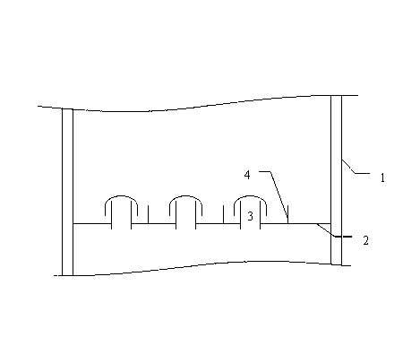
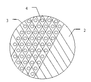
[0028] Such as figure 2 As shown, suction-type gas-liquid distributors 3 are arranged on the gas-liquid distribution tray tray 2 , and each gas-liquid distributor 3 is surrounded by a diamond-shaped liquid phase cofferdam 4 . The height of the liquid phase cofferdam is 1.0 times the height from the bottom edge of the bubble cap to the gas-liquid distribution plate 2 . When the tray 2 of the gas-liquid distribution tray is horizontally deflected, a small area of relatively independent liquid surface will be maintained between the liquid phase cofferdams 4 to ensure that the gas-liquid distributor 3 in the liquid phase cofferdams 4 can continue to function.
Embodiment 2
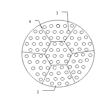
[0030] Such as image 3 As shown, suction type gas-liquid distributors 3 are arranged on the gas-liquid distribution tray 2 , and a plurality of gas-liquid distributors 3 are surrounded by a liquid phase cofferdam 4 . The liquid phase cofferdam in the middle is hexagonal, and the other liquid phase cofferdams are fan-shaped. The height of the liquid phase cofferdam is 1.2 times the height from the bottom edge of the bubble cap to the gas-liquid distribution plate 2 . When the gas-liquid distribution plate tray 2 is horizontally deflected, a small area of relatively independent liquid surface will be maintained between the liquid phase cofferdams 4 to ensure that the multiple gas-liquid distributors 3 in the liquid phase cofferdams 4 have the corresponding Adapt to the liquid level, better play a role.
Embodiment 3
[0032] Such as Figure 4 As shown, suction type gas-liquid distributors 3 are arranged on the gas-liquid distribution tray 2 , and a plurality of gas-liquid distributors 3 are surrounded by a liquid phase cofferdam 4 . The liquid phase cofferdam in the middle is circular, and the circular liquid phase cofferdam is surrounded by fan-shaped liquid phase cofferdams. The height of the liquid phase cofferdam is 1.5 times the height from the bottom edge of the bubble cap to the gas-liquid distribution plate 2 . When the gas-liquid distribution plate tray 2 is horizontally deflected, a small area of relatively independent liquid surface will be maintained between the liquid phase cofferdams 4 to ensure that the multiple gas-liquid distributors 3 in the liquid phase cofferdams 4 have the corresponding Adapt to the liquid level, better play a role.
PUM
 Abstract
Description
Claims
Application Information
 - R&D
- Intellectual Property
- Life Sciences
- Materials
- Tech Scout
- Unparalleled Data Quality
- Higher Quality Content
- 60% Fewer Hallucinations
Browse by: Latest US Patents, China's latest patents, Technical Efficacy Thesaurus, Application Domain, Technology Topic, Popular Technical Reports.
© 2025 PatSnap. All rights reserved.Legal|Privacy policy|Modern Slavery Act Transparency Statement|Sitemap|About US| Contact US: help@patsnap.com


