Radar sensor for motor vehicles, especially lca sensor

A technology of radar sensor, motor vehicle, applied in the field of radar sensor

Active Publication Date: 2013-05-08
ROBERT BOSCH GMBH
View PDF3 Cites 7 Cited by
  • Summary
  • Abstract
  • Description
  • Claims
  • Application Information

AI Technical Summary

Problems solved by technology

This allows a cost-effective construction of the radar sensor

Method used


Image

  • Radar sensor for motor vehicles, especially lca sensor
  • Radar sensor for motor vehicles, especially lca sensor
  • Radar sensor for motor vehicles, especially lca sensor

Examples


Embodiment Construction

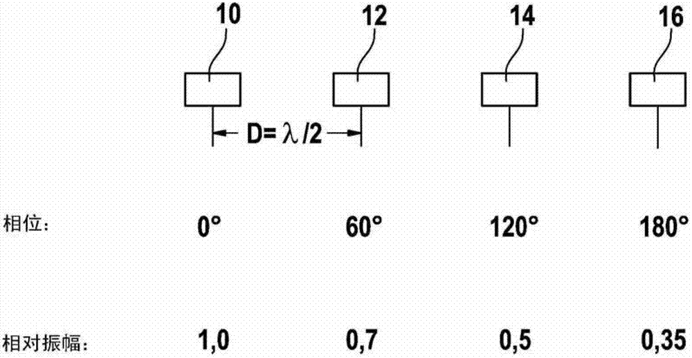
[0014] exist figure 1 4 antenna elements 10 , 12 , 14 , 16 are shown, which are arranged in horizontal rows at regular intervals on an HF substrate (not shown). The antenna elements are represented here as individual patches. Via a feed network which will be described in detail later, the antenna elements receive microwave signals which are then to be emitted as radar beams. In the example shown, the center distance d of the antenna elements is half the wavelength of the microwave radiation (d=λ / 2).

[0015] also in figure 1 The phase assignment and the amplitude assignment of the antenna elements 10, 12, 14, 16 are described in . Referring to the antenna elements 10 at the left end of the row (phase=0°), the second antenna element 12 has a phase shift of 60°, the third antenna element 14 has a phase shift of 120°, and the fourth antenna element 16 has a phase shift of 180. The phase shift is thus increased by the same increment (60°) and the antenna elements 10 and 16 at...


PUM


Abstract

Radar sensor for motor vehicles (44), comprising a transmitting antenna (Tx) in the form of a planar array antenna having a plurality of juxtaposed antenna elements (10, 12, 14, 16), and further comprising a supply network (26) for providing the antenna elements with microwave power, characterized in that the supply network (26) is designed to provide the antenna elements (10, 12, 14, 16) with microwave power that has a phase shift which increases from one end of the row to the other by constant increments.

Description

technical field [0001] The invention relates to a radar sensor for a motor vehicle having a transmitting antenna in the form of a planar composite antenna with a plurality of antenna elements arranged side by side, and a feed network. The feed network is used to deliver microwave power to the antenna elements. Background technique [0002] Radar sensor antennas provided for use in motor vehicles are usually realized as patch antennas on HF substrates. This allows a cost-effective design of the radar sensor. Through the use of combined antennas, the desired directional behavior of the radar sensor in azimuth and / or in elevation can be achieved without the need for a radar lens. Separate antennas are usually used for the transmission of radar signals and the reception of reflected signals. The desired directional behavior of the transmitting antenna in terms of azimuth can be achieved by feeding the microwave power to a plurality of antenna elements arranged next to one ano...

Claims


Application Information

Patent Timeline
IPC IPC(8): G01S13/93H01Q3/30H01Q21/06G01S13/931
CPCH01Q1/3233H01Q21/08G01S13/931H01Q3/30H01Q21/065G01S2013/9332H01Q9/0407H01Q21/06G01S2013/9315H01Q3/26H01Q3/28H01Q1/32H01Q3/34H01Q3/36
Inventor T·宾策尔
Owner ROBERT BOSCH GMBH
Why Eureka
Try Eureka