Power control method, system and device of detection reference signals
A detection reference signal and power control technology, which is applied in the field of communication, can solve problems such as waste of user transmission power, failure to obtain power control effects in time, failure to meet user coverage and reception quality requirements, etc.
- Summary
- Abstract
- Description
- Claims
- Application Information
AI Technical Summary
Problems solved by technology
Method used
Image
Examples
Embodiment 1
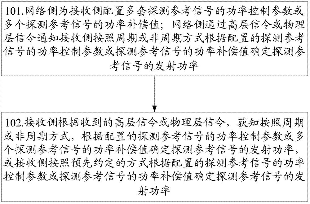
[0458] The network side configures three SRS power compensation values ΔP1, ΔP2, and ΔP3 for the receiving side through high-level signaling, which are used for SRS power compensation when the receiving side is in the non-CoMP state, uplink CoMP state, and downlink CoMP state, respectively.
[0459] The network side configures and notifies the receiving side of the SRS power control parameters in the non-CoMP state according to the existing method, and the SRS power control parameters in the non-CoMP state include at least: P SRS_OFFSET,c , indicating the power offset of the SRS in each subframe; M SRS,c , indicating the transmission band of SRS in each subframe; P O_PUSCH,c , represents the PUSCH power control parameter; α c , represents the path loss conversion factor; f c , indicating the closed-loop power control correction value of the SRS.
[0460] The receiving side calculates the uplink path loss PL according to the existing method c .
[0461] The network side ...
Embodiment 2
[0482] The network side configures three sets of SRS power control parameters (the first set of SRS power control parameters, the second set of SRS power control parameters, and the third set of SRS power control parameters) for the receiving side through high-level signaling, which are respectively used for the receiving side in non-CoMP state, uplink CoMP state, and SRS power control in downlink CoMP state.
[0483] Each set of SRS power control parameters includes at least: P SRS_OFFSET,c , indicating the power offset of the SRS in each subframe; M SRS,c , indicating the transmission bandwidth of SRS in each subframe; P O_PUSCH,c , represents the PUSCH power control parameter; α c , represents the path loss conversion factor; f c , indicating the closed-loop power control correction value of the SRS.
[0484] The receiving side determines the uplink path loss PL according to the existing method or a new method c .
[0485] The network side notifies the receiving side ...
Embodiment 3
[0500] The network side configures three sets of SRS power control parameters (the first set of SRS power control parameters, the second set of SRS power control parameters, and the third set of SRS power control parameters) for the receiving side through high-level signaling, which are respectively used for the receiving side in non-CoMP state, uplink CoMP state, and SRS power control in downlink CoMP state.
[0501] Each set of SRS power control parameters includes at least: P SRS_OFFSET,c , for the power offset of SRS in each subframe; M SRS,c , used for the transmission bandwidth of SRS in each subframe; P O_PUSCH,c , used for PUSCH power control parameters; α c , used for path loss conversion factor; f c , used for the closed-loop power control correction value of SRS.
[0502] The receiving side determines the uplink path loss PL according to the existing method or a new method c .
[0503] The network side and the receiving side cyclically determine the transmit p...
PUM
 Abstract
Description
Claims
Application Information
 - R&D
- Intellectual Property
- Life Sciences
- Materials
- Tech Scout
- Unparalleled Data Quality
- Higher Quality Content
- 60% Fewer Hallucinations
Browse by: Latest US Patents, China's latest patents, Technical Efficacy Thesaurus, Application Domain, Technology Topic, Popular Technical Reports.
© 2025 PatSnap. All rights reserved.Legal|Privacy policy|Modern Slavery Act Transparency Statement|Sitemap|About US| Contact US: help@patsnap.com


