
Electronic equipment and touch control method thereof

An electronic device, touch technology, applied in electrical digital data processing, instruments, computing, etc., can solve problems such as unfriendly experience, area difference, difference, etc., to improve human-machine friendliness, improve ease of use, and avoid mistakes. touch effect

Inactive Publication Date: 2013-05-08
LENOVO (BEIJING) CO LTD
View PDF4 Cites 51 Cited by
  • Summary
  • Abstract
  • Description
  • Claims
  • Application Information

AI Technical Summary

Problems solved by technology

These technologies have a common shortcoming, that is, they cannot measure the real pressure of the user's touch operation.
[0003] For example, on a capacitive touch screen, the pressure of the user's operation is indirectly measured by detecting the contact area of ​​the user's finger. If the contact area is large, the pressure is considered to be large, and if the contact area is small, the pressure is considered to be small; in this way, the difference in the finger area of ​​different users is relatively large. large, and the areas of different fingers of the same user are also quite different; or the same finger is at different touch angles, even if the user's force is the same, the area in contact with the touch screen will be very different, so that The pressure felt by the touch screen is also very different, so that the same operation cannot be performed correctly due to the different pressures detected by the touch screen, which brings great trouble to the user
[0004] In addition, if the user accidentally touches the touch screen or touch keys by mistake, the touch screen or touch keys cannot be judged as a misoperation at all, and it is still recognized according to normal touch, which brings an unfriendly experience to the user

Method used


Image

  • Electronic equipment and touch control method thereof
  • Electronic equipment and touch control method thereof
  • Electronic equipment and touch control method thereof

Examples


no. 1 example

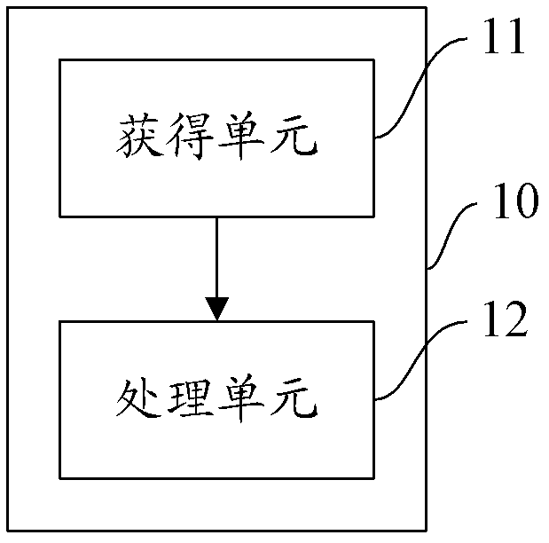
[0031] A kind of electronic equipment 10, this electronic equipment comprises:

[0032] The obtaining unit 11 is configured to obtain a pressure signal generated when the user performs a touch operation, wherein the pressure signal includes the coordinates of the touch point of the touch operation and the magnitude of the pressure;

[0033] The processing unit 12 is configured to, according to the magnitude of the pressure in the pressure signal, execute corresponding operations of the application corresponding to the coordinates of the point of application, the application being the application currently displayed on the electronic device.

[0034] In the first embodiment of the present invention, the pressure signal includes the coordinates of the force point of the touch operation and the magnitude of the pressure; the pressure signal will be transmitted to the processing unit, and the processing unit of the electronic device will Size, execute the corresponding operation o...


PUM


Abstract

The invention provides electronic equipment and a touch control method thereof. The electronic equipment comprises a receiving unit and a processing unit. The receiving unit is used for receiving pressure signals generated during touching operation which is performed by a user; the pressure signals comprise coordinates of a stress point and pressure of the touching operation; the processing unit is used for performing operations corresponding to applications which correspond to the coordinates of the stress point; and the applications are currently displayed in the electronic device. The electronic device and the touch control method thereof has the advantages of achieving more functions of a touch screen furthest, avoiding error touch, bringing novel interactive experiences to the user, improving usability of products and improving man-machine friendliness of the electronic device.

Description

technical field [0001] The present invention relates to touch technology, in particular to an electronic device and a touch method thereof. Background technique [0002] Touch screens and touch buttons are widely used in electronic products, mainly divided into resistive, capacitive, acoustic, infrared reflective, optical and other methods. These technologies have a common shortcoming, that is, they cannot measure the real pressure of the user's touch operation. [0003] For example, on a capacitive touch screen, the pressure of the user's operation is indirectly measured by detecting the contact area of ​​the user's finger. If the contact area is large, the pressure is considered to be large, and if the contact area is small, the pressure is considered to be small; in this way, the difference in the finger area of ​​different users is relatively small. large, and the areas of different fingers of the same user are also quite different; or the same finger is at different to...

Claims


Application Information

Patent Timeline
IPC IPC(8): G06F3/041
Inventor 刘湘涛
Owner LENOVO (BEIJING) CO LTD
Learn More