Balancing double-switching circuit and insulation detection device and method based on the same

A detection device, double switching technology, applied in measurement device, grounding resistance measurement, measurement of resistance/reactance/impedance, etc., can solve the problems of inability to realize real-time detection of system insulation status, false detection, low insulation resistance, etc.

Active Publication Date: 2013-05-08
ZHEJIANG CN CO2 TECH
View PDF6 Cites 41 Cited by
  • Summary
  • Abstract
  • Description
  • Claims
  • Application Information

AI Technical Summary

Problems solved by technology

However, when the balance resistor is selected as a small resistor of the kilohm level, the insulation resistance of the busbar to the ground will be too small, posing a safety hazard
When the switching resistance is selected as a large resistance of megohm level, the leakage current value will be too small, which will affect the calculation accuracy of the branch resistance
[0005] In addition, existing insulation detection systems generally use a fixed detection cycle for insulation detection. When the system is grounded, this method may not immediately perform insulation detection, so that real-time detection of system insulation status cannot be realized.
[0006] Third, insulation testing takes a certain amount of time, and the grounding status of the system may change during the testing process. Once a change occurs, if the original testing steps are used to continue testing, the final detected result will not be the insulation of the current system. condition, false detection
[0007] Fourth, the current leakage sensor has the disadvantage of zero drift, and directly reading the value of the leakage sensor as the leakage data of the branch to calculate the insulation resistance of the branch will lead to inaccurate calculation results

Method used


Image

  • Balancing double-switching circuit and insulation detection device and method based on the same
  • Balancing double-switching circuit and insulation detection device and method based on the same
  • Balancing double-switching circuit and insulation detection device and method based on the same

Examples


Embodiment Construction

[0058] The detection device and detection method of the present invention will be further described below in conjunction with the accompanying drawings with actual detection examples.

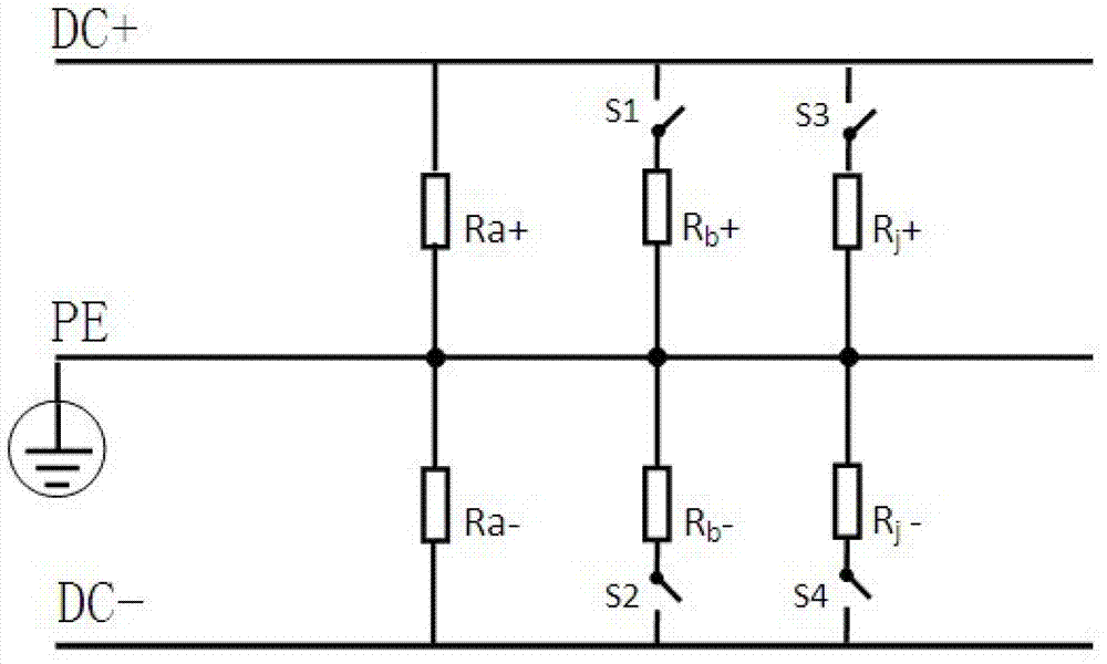
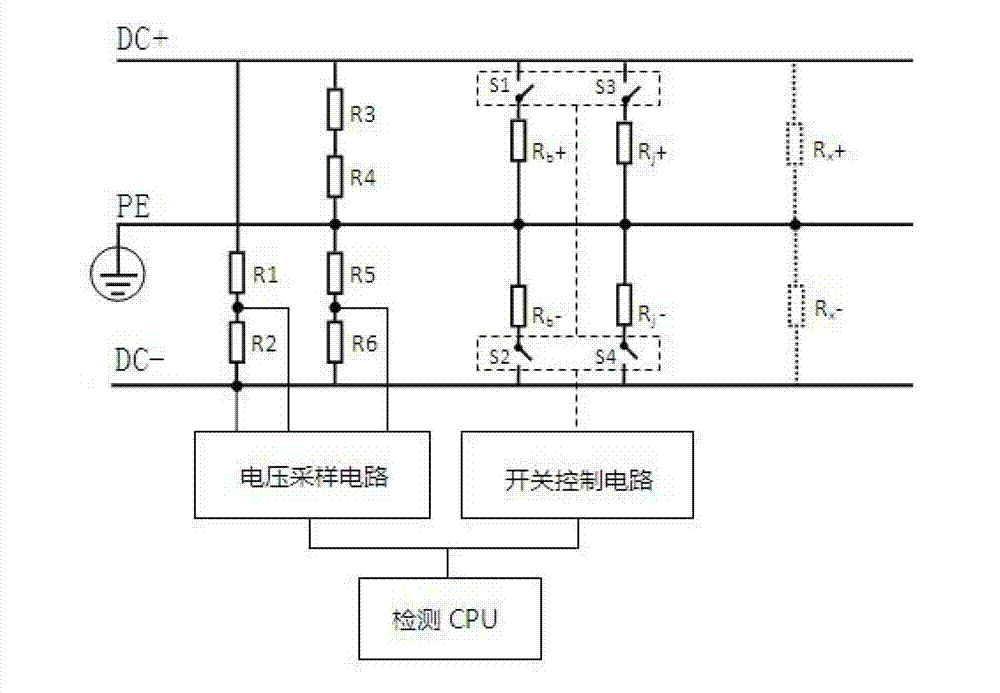
[0059] figure 2 It is a schematic diagram of a real-time insulation detection device for a DC power supply system of the present invention. In the figure, DC+ indicates a positive bus, DC- indicates a negative bus, and PE indicates ground. Resistors R1 and R2 are detection resistors for bus voltage, R1>>R2. Resistors R5 and R6 are detection resistors for negative bus-to-ground voltage, R5>>R6. Resistors R3, R4, R5, R6 constitute the voltage dividing resistor between the ground and the positive and negative bus bars, and R3+R4=R5+R6. Resistance R b + is the balance resistance between the positive busbar and the ground, which is closed and disconnected by the switch S1, and the resistance R b - is the balance resistance between the negative bus and the ground, which is controlled by the swit...


PUM


Abstract

The invention belongs to the technical field of electrical equipment measuring and testing, and discloses a balancing double-switching circuit used for insulation detection of a direct current power supply system. A resistor with meg-ohm-level big resistance values of the balancing double-switching circuit is used as a frequently-used balancing resistor, and a kilo-ohm resistor with small resistance values is capable of being cut off and is in parallel connection with the frequently-used balancing resistor, and is cut in when high-accuracy detection is needed to reduce the resistance value between a bus and the ground and ensure that the resistance value between the bus and the ground differs little to that of a switching resistor, and therefore the extreme condition that because the voltage sampling end is too small and the like, detection accuracy is affected is avoided. The balancing double-switching circuit is adopted to conduct insulation detection, and therefore on the basis that equipment almost guarantees requirements of insulation against ground, insulation detection accuracy is effectively improved and error alarm is reduced.

Description

technical field [0001] The invention belongs to the field of electrical equipment measurement and testing, and relates to a technology for real-time detection of the insulation status of a DC power supply system. Background technique [0002] DC power supply systems have been widely used in various computer rooms to supply power to servers. Ground faults in electrical equipment or power distribution cabinets are common faults. Accurately discovering the ground fault point plays a great role in the rapid repair and elimination of faults by the power maintenance and repair unit. [0003] At present, the commonly used method for insulation detection of DC power system is the unbalanced switching method. Connect a pair of balance resistors between the positive and negative bus bars and the ground, and use the voltage value at both ends of the balance resistors as the sampled value, and at the same time connect a switching switch and a switching resistor in series between the po...

Claims


Application Information

Patent Timeline
IPC IPC(8): G01R31/02G01R31/08G01R27/20G01R27/08
Inventor 沈亚斌
Owner ZHEJIANG CN CO2 TECH
Why Eureka
Try Eureka