
Fatigue testing machine for torsion spring

A fatigue testing machine and torsion spring technology, used in measuring devices, instruments, scientific instruments, etc., can solve the problems of large data differences, low test efficiency, and high preparation costs, and achieve reduced preparation costs, high test efficiency, and reduced test. cost effect

Active Publication Date: 2013-05-08
NINGBO YONGXIN AUTO COMPONENTS MFG
View PDF4 Cites 11 Cited by
  • Summary
  • Abstract
  • Description
  • Claims
  • Application Information

AI Technical Summary

Problems solved by technology

The torsion spring fatigue testing machine of the prior art is not complicated in structure, has many parts, is not easy to assemble, and has high preparation cost; it is relatively simple in structure, requires workers to manually carry out the test, and the stability during the test is relatively poor. The data difference during use is relatively large; and the torsion spring fatigue testing machine of the prior art can only carry out the fatigue test to a torsion spring at a time, so the test efficiency is low

Method used


Image

  • Fatigue testing machine for torsion spring
  • Fatigue testing machine for torsion spring
  • Fatigue testing machine for torsion spring

Examples


Embodiment Construction

[0014] The present invention will be further described below in conjunction with the accompanying drawings and specific embodiments.

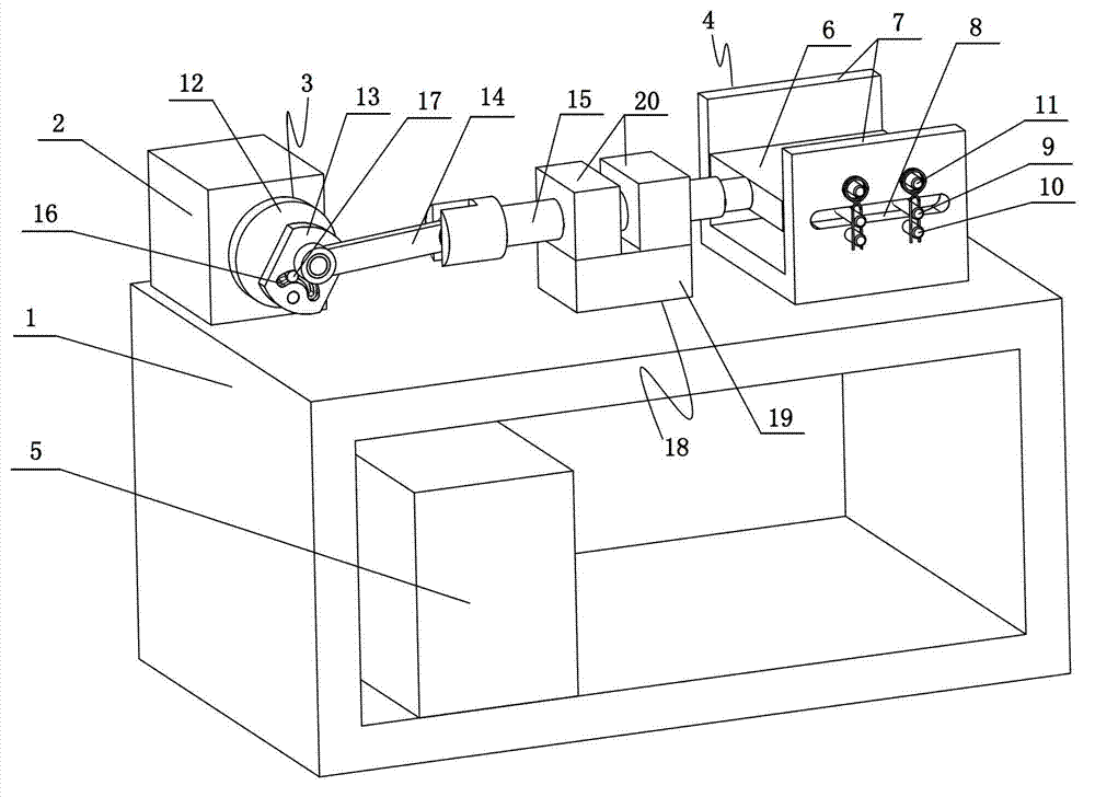
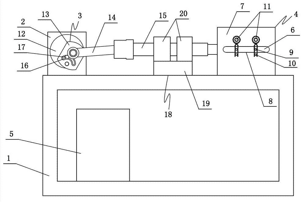
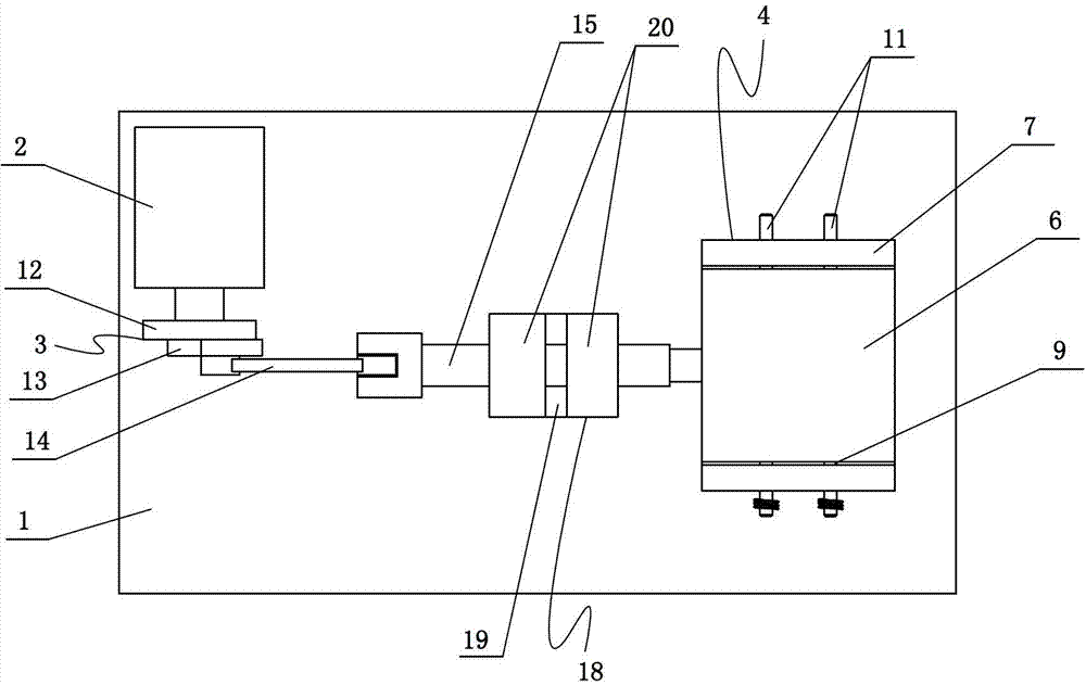
[0015] Such as figure 1 , figure 2 and image 3 A kind of torsion spring fatigue testing machine shown, it comprises frame 1, motor 2, transmission mechanism 3 and torsion spring clamp 4, described motor 2 and torsion spring clamp 4 are all fixed on the frame 1, and motor 2 and torsion spring clamps 4 are located at both ends of the upper end face of the frame 1, the transmission mechanism 3 is connected to the output shaft of the motor 2, the bottom of the frame 1 is provided with a control box 5, and the motor 2 is connected to the control box 5 connections, the torsion spring clamp 4 includes a sliding plate 6 and at least one fixed plate 7 (two in this example, but also one, three, four or five, etc.), the fixed plate 7 Vertically fixed on the upper end surface of the frame 1, and the plane of the fixed plate 7 is perpendicular to the a...


PUM


Abstract

The invention relates to a fatigue testing machine for a torsion spring. According to the fatigue testing machine, a torsion spring fixture (4) comprises a sliding plate (6) and at least one fixing plate (7), wherein the fixing plates (7) are vertically fixed at the upper end face of a stander (1), and the planes of the fixing plates (7) are vertical to the axis of an output shaft of a motor (2); at least one deflector rod (9) is arranged at one side of the sliding plate (6), close to the fixing plates (7), the middle parts of the deflector rods (9) are connected into sliding chutes (8) in a sliding way, limiting rods (10) in one-to-one correspondence with the deflector rods (9) are arranged on the planes of the fixing plates (7) above the free ends of the deflector rods (9), sleeving rods (11) for sleeving the torsion spring are arranged right below the limiting rods (10) on the planes of the fixing plates (7), the sliding chutes (8) are located between the limiting rods (10) and the sleeving rods (11), and the distances between the limiting rods (10) and the sleeving rods (11) are shorter than the length of a twisted foot of the torsion spring. Compared with the prior art, the fatigue testing machine has the characteristics that the structure is simpler, the parts and components are fewer, the stability is better, the obtained test data is closer to an actual use condition, and the test efficiency is higher.

Description

technical field [0001] The invention relates to a torsion spring fatigue testing machine. Background technique [0002] At present, torsion springs are widely used in various fields, and the failure of torsion springs is generally fatigue failure, so the fatigue test of torsion springs is more important. The torsion spring fatigue testing machine of the prior art is not only complicated in structure, has many parts, is not easy to assemble, and has high preparation costs; it is relatively simple in structure, requires workers to manually carry out the test, and has poor stability during the test. The data difference during use is relatively large; and the torsion spring fatigue testing machine of the prior art can only carry out the fatigue test to one torsion spring at a time, so the test efficiency is low. Contents of the invention [0003] Aiming at the above problems, the present invention provides a torsion spring fatigue testing machine with a simpler structure, few...

Claims


Application Information

Patent Timeline
Patent Type & Authority Applications(China)
IPC IPC(8): G01N3/00G01N3/02
Inventor 张阳才鲍鹏州王昌武叶浩梁
Owner NINGBO YONGXIN AUTO COMPONENTS MFG
Learn More