
Structure for reducing back pressure of air inlet channel of inspiration type impulse knocking engine

A pulse detonation, engine technology, applied in engine components, air inlets of turbine/propulsion, combustion air/combustion-air processing, etc. The valve structure is complicated, etc.

Inactive Publication Date: 2013-05-08
NORTHWESTERN POLYTECHNICAL UNIV
View PDF4 Cites 15 Cited by
  • Summary
  • Abstract
  • Description
  • Claims
  • Application Information

AI Technical Summary

Problems solved by technology

Existing pneumatic valves such as the Srnirnov conical pneumatic valve have great forward air intake resistance, while the swirler-type pneumatic valve has a complex structure, and the blades are easily deformed after being subjected to periodic pulse pressure
In conclusion, the use of pneumatic valves to reduce intake back pressure still needs a lot of research work

Method used


Image

  • Structure for reducing back pressure of air inlet channel of inspiration type impulse knocking engine
  • Structure for reducing back pressure of air inlet channel of inspiration type impulse knocking engine
  • Structure for reducing back pressure of air inlet channel of inspiration type impulse knocking engine

Examples


Embodiment Construction

[0023] Describe the present invention below in conjunction with specific embodiment:

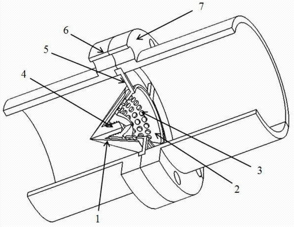
[0024] Refer to attached Figure 5 , the structure proposed by the present invention to reduce the intake port back pressure of an air-breathing pulse detonation engine is applied in the mixing chamber and ignition chamber of the engine in this embodiment.

[0025] Refer to attached figure 1 , the structure for reducing the backpressure of the air intake pulse detonation engine consists of a front cone 1 and a rear cone 2 .

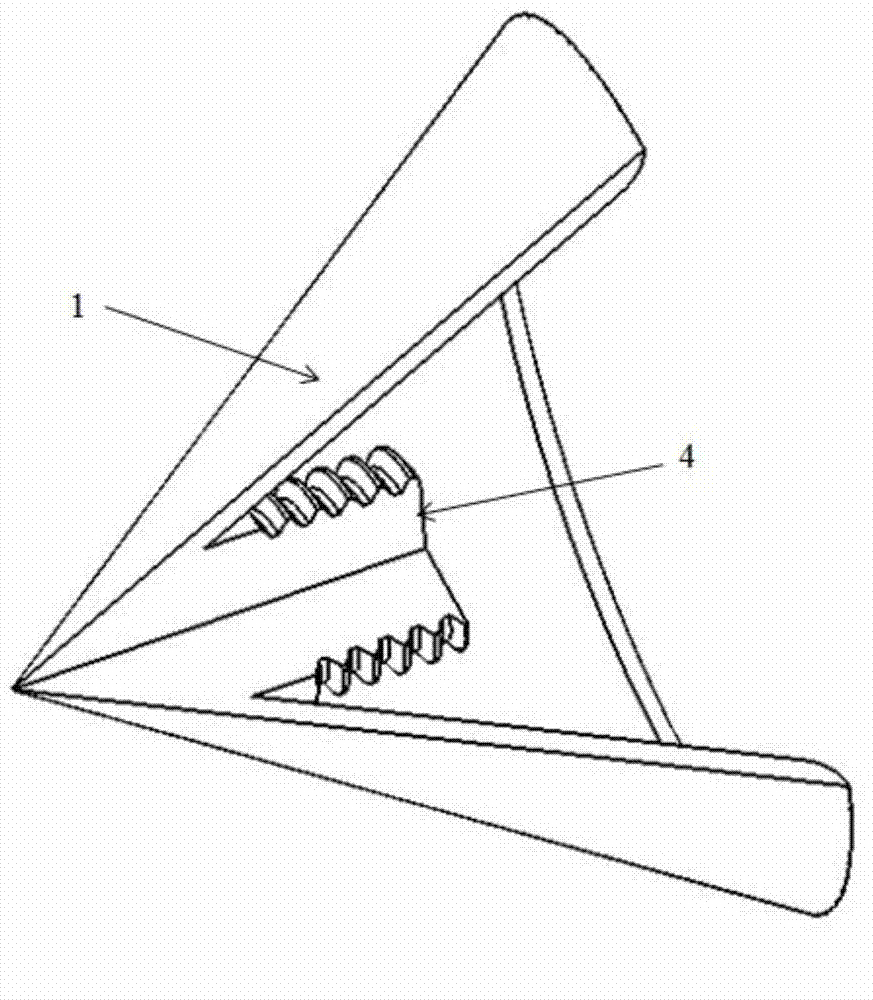
[0026] Refer to attached figure 2 , the front cone 1 is a thin-walled conical structure, and there is an axial cylinder 4 with external threads on the inner surface of the front cone head, and the axis of the cylinder 4 coincides with the axis of the front cone.

[0027] Refer to attached image 3 , the back cone 2 is a thin-walled conical structure, with an axial boss on the inner surface of the back cone head, and an axial blind hole with internal threads on the ...


PUM


Abstract

The invention provides a structure for reducing back pressure of an air inlet channel of an inspiration type impulse knocking engine. The structure is composed of a front cone and a rear cone, wherein the inner surface of the head of the front cone is provide with an axial column with an external thread, the inner surface of the head of the rear cone is provided with an axial boss, and the outer surface of the head of the rear cone is provided with an axial internal thread blind hole; the wall surface of the rear cone is provided with a plurality of drainage holes, the axial column of the external thread of the front cone and the blind hole of the internal thread of the rear cone are matched and fixed so as to form a conical ring cavity; pressure wave formed by combustion flame can reflect the pressure wave on the boss of the rear cone in use, and the transition from slow combustion to knocking is capable of accelerated; the knocking wave is formed, the knocking wave is spread on the rear cone, intense shock wave generated by the rear cone through reflecting is spread to the outlet, and the reflux total pressure is reduced; reflux enters the rear cone so as to enter the conical ring cavity through drainage holes and flow out along a ring cavity, and the flowing direction of part reflux is changed; and the reflux flowed from the ring cavity forms an annular jet, the reflux and the reflux through bypassing the rear cone are mutually acted, and the reflux discharge and total pressure of forward spread are reduced.

Description

technical field [0001] The invention relates to the technical field of engines, in particular to a structure for reducing the back pressure of an intake port of an air-breathing pulse detonation engine. Background technique [0002] A pulse detonation engine is a power device that works periodically. Pulse detonation engines can be divided into air-breathing pulse detonation engines and rocket-type pulse detonation engines according to whether they have their own oxidant. As the air-breathing pulse detonation engine needs to periodically inhale air as the oxidant, its air inlet cannot be completely closed. [0003] After the air-breathing pulse detonation engine is ignited, before a stable detonation wave is formed, several local high-temperature and high-pressure areas (hot spots) will be formed in the detonation chamber, and then a stable detonation wave will be formed and propagate to the engine outlet. However, the local high-pressure area will also form a shock wave t...

Claims


Application Information

Patent Timeline
Patent Type & Authority Applications(China)
IPC IPC(8): F02C7/04
Inventor 郑龙席卢杰王治武陈星谷彭畅新
Owner NORTHWESTERN POLYTECHNICAL UNIV
Learn More