
Robot programming device

A technology for programming devices and manipulators, applied in manipulators, program control manipulators, program control, etc., can solve problems such as a large amount of time in three-dimensional space

Active Publication Date: 2013-05-08
FANUC LTD
View PDF12 Cites 11 Cited by
  • Summary
  • Abstract
  • Description
  • Claims
  • Application Information

AI Technical Summary

Problems solved by technology

Therefore, the adjustment work in the three-dimensional space also takes a lot of time

Method used


Image

  • Robot programming device
  • Robot programming device
  • Robot programming device

Examples


Embodiment Construction

[0031] Hereinafter, embodiments of the present invention will be described with reference to the drawings. In the following drawings, the same reference numerals are given to the same components. For easy understanding, the reduced scale of these drawings is appropriately changed.

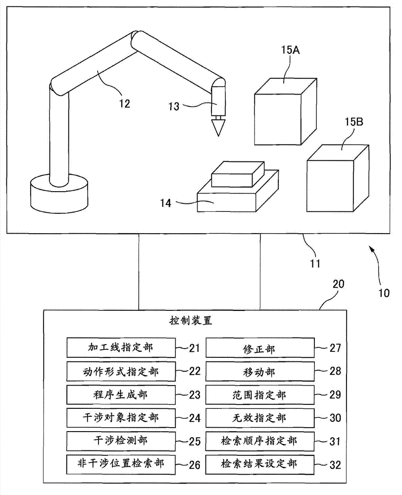
[0032] figure 1 It is a schematic diagram of the robot programming device according to the first embodiment of the present invention. The robot programming device 10 mainly includes a display unit 11 (such as a liquid crystal display, CRT), and a control device 20 (such as a digital computer) connected to the display unit 11 .

[0033] figure 1 , a three-dimensional model of the manipulator 12 (for example, a multi-joint manipulator) and a three-dimensional model of the tool 13 attached to the tip of the manipulator 12 are displayed on the display unit 11 . The tool 13 differs depending on the work performed by the manipulator 12, for example, deburring work, arc welding, and the like.

[0034...


PUM


Abstract

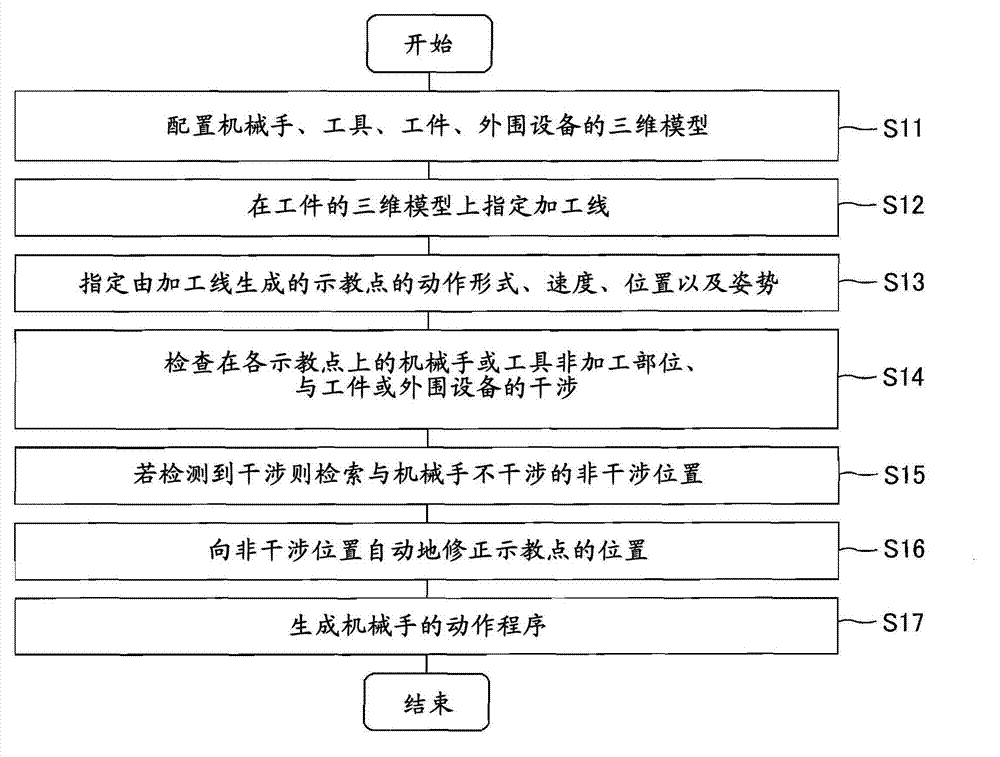
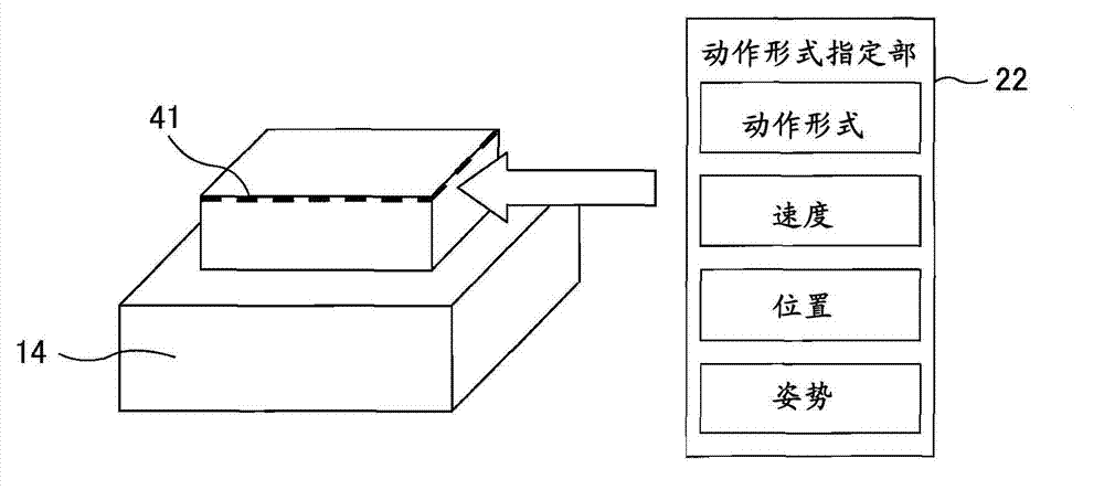
A robot programming device (10) includes: a processing line designating unit (21) that designates a processing line (41); an operation mode designating unit (22) that designates an operation mode of the teaching point; a program generation unit (23) that generates a program for a robot (12) based on the processing line and the operation mode; an interference target designating unit (24) that designates a tool non-processing part as an interference target; an interference detection unit (25) that detects interference between the robot and the workpiece, at a teaching point; a non-interference position search unit (26) that searches for a non-interference position; and a correction unit (27) that corrects a position of the teaching point based on a search result.

Description

technical field [0001] The present invention relates to a manipulator programming device which arranges and simultaneously displays three-dimensional models of a manipulator on which a tool is mounted, a workpiece, and at least one peripheral device on a screen, and teaches an operation program of the manipulator so that the workpiece or the manipulator avoids contact with the workpiece Or the interference of the above-mentioned peripheral equipment is performed while processing the workpiece, and the operation is performed offline. Background technique [0002] In recent years, there has been an increase in the use of off-line programming methods for manipulator teaching operations. In such a method, the machining line to be machined of the workpiece is specified on the CAD model of the workpiece, and conditions such as tool posture and motion speed are specified to generate teaching points. After that, the operator performs correction while checking the interference betwe...

Claims


Application Information

Patent Timeline
Patent Type & Authority Applications(China)
IPC IPC(8): B25J9/16
CPCG05B2219/40317B25J9/1671G05B19/4097G05B2219/40507G05B2219/40107Y02P90/02G05B19/4061
Inventor 后平宽之
Owner FANUC LTD
Learn More