
Brake system for motor vehicles

A technology for braking systems, motor vehicles, applied in the direction of braking control systems, braking safety systems, brakes, etc., to solve problems such as failures, failures of electronic units, and even power failures

Inactive Publication Date: 2013-05-01
CONTINENTAL TEVES AG & CO OHG
View PDF4 Cites 34 Cited by
  • Summary
  • Abstract
  • Description
  • Claims
  • Application Information

AI Technical Summary

Problems solved by technology

Thus, a vehicle equipped with this "by-wire" braking system can also be braked in the event of a failure of the pressure generating device, in the event of a failure of the electronic unit and even in the event of a failure of the power supply, but in this case only using the The set energy provided by the driver through actuation of the brake pedal

Method used


Image

  • Brake system for motor vehicles

Examples


Embodiment Construction

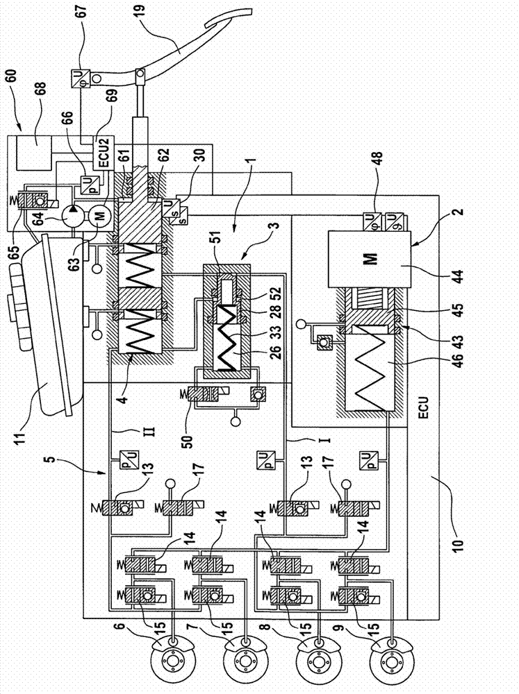
[0023] An embodiment of the braking system according to the invention as shown in the figures is described in more detail below. The electrohydraulic braking system shown as an example in the figure essentially comprises an actuating device 1 with a brake master cylinder 4 connected in series and an analog device 3 , an electronically controllable pressure generating device 2 , a wheel brake pressure modulating device or a pressure regulating valve device 5 , and an electronic control and regulation unit (ECU) 10 . The wheel brakes 6 , 7 , 8 , 9 are connected to a wheel brake pressure modulation device 5 . The pressure chamber of master brake cylinder 4 can be connected to a pressure medium reservoir 11 at atmospheric pressure. The wheel brakes 6, 7, 8, 9 are assigned to brake circuits I, II, so that the wheel brakes 8, 9 connected to the first brake circuit I are assigned to one axle, while the wheel brakes connected to the second brake circuit II The wheel brakes 6, 7 serv...


PUM


Abstract

In a brake system for motor vehicles, having a master brake cylinder (4) which can be actuated by means of a brake pedal (19) and to which wheel brakes (6, 7, 8, 9) are connected, having an electrically controllable pressure generating device (2), having a pressure regulating valve arrangement (5) for regulating and / or controlling a wheel brake pressure induced at a wheel brake (6, 7, 8, 9), and having a first electronic control and regulating unit (10) which controls or regulates the pressure generating device (2) and / or the pressure regulating valve arrangement (5), it is sought to a provide brake force assistance means which is independent of the functioning of the pressure generating device. For this purpose, said brake system comprises an electrically controllable auxiliary pressure generating device (60) by means of which the master brake cylinder (4) can be actuated, in particular by means of which a pressure in an intermediate chamber (61) of the master brake cylinder (4) can be controlled or regulated.

Description

technical field [0001] The invention relates to a brake system for a motor vehicle comprising: a brake master cylinder actuatable by means of a brake pedal and connected to the wheel brakes; an electrically controllable pressure generating device; for regulating and / or controlling the a pressure regulating valve arrangement for the wheel brake pressure set on the wheel brakes; and a first electronic control and regulating unit for controlling or regulating the pressure generating device and / or the pressure regulating valve arrangement. Background technique [0002] In automotive technology, "brake-by-wire" braking systems are becoming more and more common. Brake systems of this type often include a pedal decoupling unit, which is connected upstream of the brake master cylinder, whereby actuation of the driver's brake pedal in the "brake-by-wire" operating mode causes the brake master cylinder to communicate with the wheel brakes. The direct hydraulic connection is disconnec...

Claims


Application Information

Patent Timeline
Patent Type & Authority Applications(China)
IPC IPC(8): B60T7/04B60T11/20B60T13/68B60T17/18
CPCB60T7/042B60T7/06B60T8/441B60T11/20B60T13/662B60T13/745B60T2270/82B60T13/686B60T17/18B60T2270/402B60T8/4081B60T7/04B60T13/68
Inventor S·林肯巴赫S·A·德鲁姆
Owner CONTINENTAL TEVES AG & CO OHG
Learn More