
Fault current limiter on basis of combined rapid switch-on switch

A closing switch, fault current technology, applied in emergency protection circuit devices, electrical components, circuit devices for limiting overcurrent/overvoltage, etc., can solve the problem of high cost, achieve fast response, market competitiveness, The effect of reducing the short-circuit capacity

Inactive Publication Date: 2013-05-01
INST OF ELECTRICAL ENG CHINESE ACAD OF SCI
View PDF5 Cites 30 Cited by
  • Summary
  • Abstract
  • Description
  • Claims
  • Application Information

AI Technical Summary

Problems solved by technology

However, all the capacitor bypass circuits mentioned above need to pass close to the full short-circuit current. Therefore, the components of the capacitor bypass circuit need to be designed to withstand the full short-circuit current, and the cost is very high.

Method used


Image

  • Fault current limiter on basis of combined rapid switch-on switch
  • Fault current limiter on basis of combined rapid switch-on switch
  • Fault current limiter on basis of combined rapid switch-on switch

Examples


Embodiment Construction

[0034] The present invention will be further described below in conjunction with the accompanying drawings and specific embodiments.

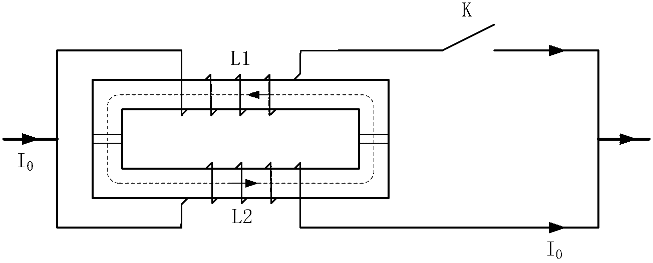
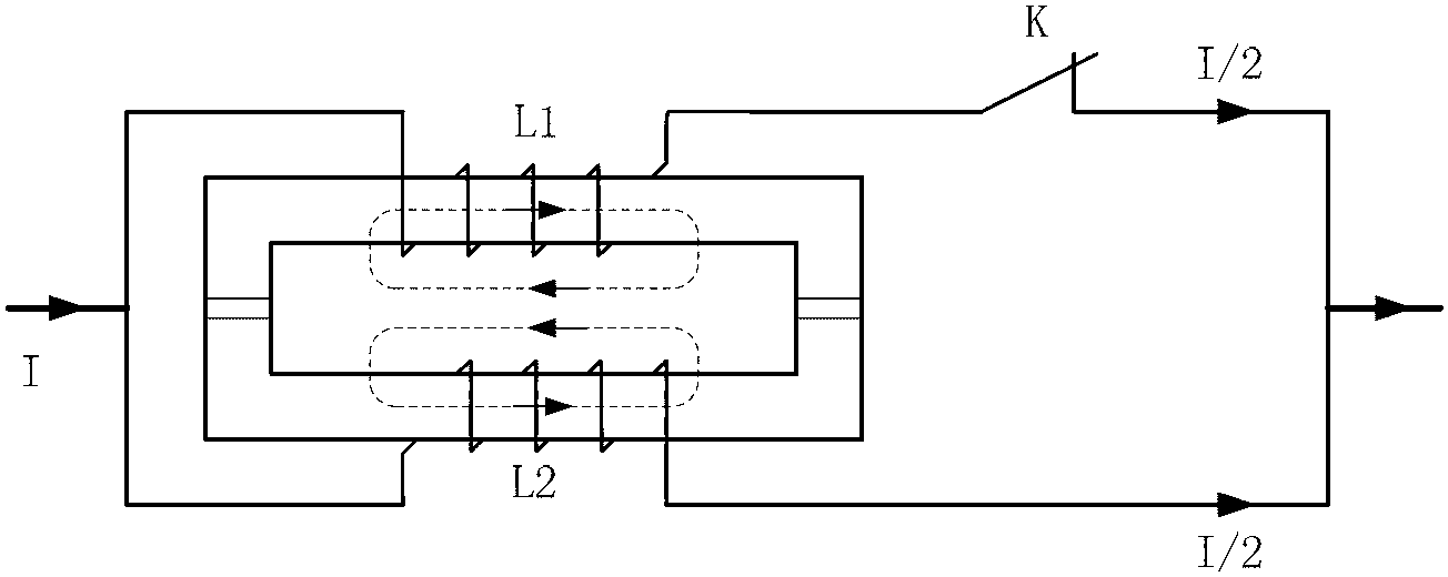
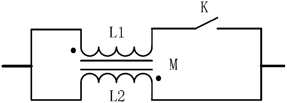
[0035] The fault current limiter based on the combined fast closing switch of the present invention is composed of a conventional reactor or a close-coupled double-winding reactor with the same name and end, a capacitor and a combined fast closing switch. The combined fast closing switch is composed of a double-winding reactor with opposite ends of the same name and a fast closing switch K.

[0036] figure 1 Shown is the circuit and magnetic circuit diagram of the combined fast closing switch in steady state operation. Such as figure 1 As shown, the combined fast closing switch is composed of a double-winding reactor with the opposite end of the same name and a fast closing switch K. The double-winding reactor with the opposite end of the same name is composed of the first winding L1, the second The winding L2 is composed of a rectangular ai...


PUM


Abstract

The invention relates to a fault current limiter on the basis of a combined rapid switch-on switch. The combined rapid switch-on switch is firstly connected in parallel with a capacitor C and then is connected in series with a conventional reactor L; the combined rapid switch-on switch is formed by combining a tight coupling double-winding reactor and a rapid switch-on switch, of which dotted terminals are opposite; a first winding L1 of the tight coupling double-winding reactor is firstly connected in series with the rapid switch-on switch and then is connected in parallel with a second winding L2; the rapid switch-on switch is formed by connecting one group or a plurality of groups of mechanical switches K, transistors T, controllable trigger gaps G and lightning arresters MOV in parallel; and in the case of a short circuit fault, switch-on on the first winding L1 of the tight coupling double-winding reactor can be implemented by selecting the rapid switch-on switch with tolerance to a low short circuit current. After the first winding L is conducted, reactances generated by the first winding L1 and the second winding L2 of the tight coupling double-winding reactor are balanced out mutually, so that the reactances are reduced.

Description

technical field [0001] The invention relates to a fault current limiter. Background technique [0002] With the rapid development of the national economy, the society's demand for electricity continues to increase, which drives the continuous development of the power system. The capacity of single machines and power plants, the capacity of substations, and the load of cities and industrial centers continue to increase, which makes the interconnection of power systems , the level of short-circuit current in the power grid at all levels is increasing continuously, and the destructiveness of short-circuit faults to the power system and its connected electrical equipment is also increasing. Moreover, while the demand for electric energy is increasing day by day, people also put forward higher requirements for power quality, power supply reliability and security. However, the transient stability of large power grids is more prominent, and one of the most important reasons is tha...

Claims


Application Information

Patent Timeline
IPC IPC(8): H02H9/02H02H9/04
CPCH02H9/02H02H9/04
Inventor 肖立业邱清泉张志丰林良真戴少涛严萍王珏夏东李耀华
Owner INST OF ELECTRICAL ENG CHINESE ACAD OF SCI
Learn More