
A low-loss split reactance current-limiting circuit breaker

A split reactance and reactor technology, applied in the power field, can solve the problems of low arc voltage, difficulty in current transfer, steady-state voltage drop and steady-state loss of power electronic switches, reduce volume and cost, and avoid difficulty in current transfer and loss low effect

Active Publication Date: 2022-08-09
INST OF ELECTRICAL ENG CHINESE ACAD OF SCI +2
View PDF15 Cites 0 Cited by
  • Summary
  • Abstract
  • Description
  • Claims
  • Application Information

AI Technical Summary

Problems solved by technology

Chinese utility model patent 201720553371.1 proposes a split reactor current limiter with a bypass circuit breaker, which can reduce the volume and loss of the split reactor, but the bypass circuit breaker generally uses a fast vacuum circuit breaker, the arc voltage is very low, and the current transfer is difficult
Chinese invention patent 201810285551.5 proposes a split reactance current limiter with a bypass circuit breaker in series with a power electronic switch. Although the volume and loss of the split reactor can be reduced and fast current transfer can be achieved, the power electronic switch has a steady-state voltage drop and steady-state losses

Method used


Image

  • A low-loss split reactance current-limiting circuit breaker
  • A low-loss split reactance current-limiting circuit breaker
  • A low-loss split reactance current-limiting circuit breaker

Examples


Embodiment Construction

[0020] The technical solutions in the embodiments of the present invention will be clearly and completely described below with reference to the accompanying drawings in the embodiments of the present invention. Obviously, the described embodiments are only a part of the embodiments of the present invention, rather than all the embodiments. Based on the embodiments of the present invention, all other embodiments obtained by persons of ordinary skill in the art without creative efforts shall fall within the protection scope of the present invention.

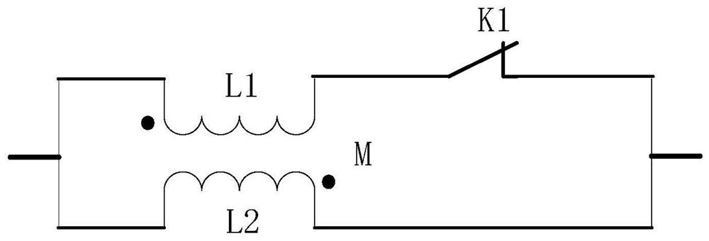
[0021] figure 1 Shown is the equivalent circuit diagram of the conventional split reactance type current limiter. The first winding L1 and the first circuit breaker K1 of the tightly coupled double-winding reactor are first connected in series, and then connected in parallel with the second winding L2. The breaking capacity can be A circuit breaker with a short-circuit current of 50% can break a single branch winding. After the fi...


PUM


Abstract

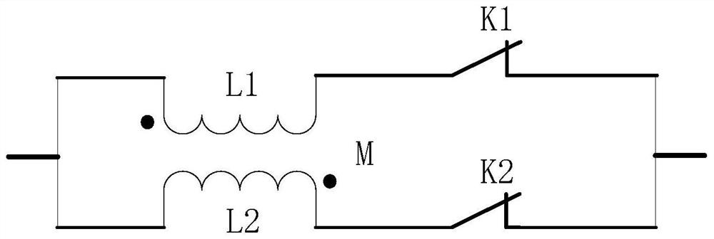
The present invention proposes a low-loss split reactance current-limiting circuit breaker, including a main circuit and a current transfer circuit, the main circuit and the current transfer circuit are connected in parallel, the main circuit is composed of a circuit breaker Ks and a reactor Ls in series, and the current transfer circuit It includes n close-coupled double-winding reactor current-limiting modules, the close-coupled double-winding reactor current-limiting module is composed of a close-coupled double-winding reactor and a circuit breaker module in series, n≥1; wherein, the current transfer loop The current limiter mode is adopted: the first winding Ln1 of the tightly coupled double-winding reactor and the first circuit breaker Kn1 are connected in series first, and then connected in parallel with the second winding Ln2 of the tightly coupled double-winding reactor to form the current limiting of the tightly coupled double-winding reactor. Module; when the circuit breaker mode is adopted, the first winding Ln1 of the tightly coupled double-winding reactor is connected in series with the first circuit breaker Kn1, the first winding Ln2 of the tightly coupled double-winding reactor is connected in series with the second circuit breaker Kn2, and then the two branches are connected in series. Connect in parallel to form a close-coupled double-winding reactor breaking module.

Description

technical field [0001] The invention belongs to the field of electric power, and particularly relates to a low-loss current-limiting circuit breaker. Background technique [0002] With the rapid development of the national economy, the social demand for electricity continues to increase, which drives the continuous development of the power system. interconnected, the short-circuit current levels in the power grids at all levels continue to increase. Even so, the general practice is to use circuit breakers to disconnect the faulty line, on the one hand to protect the power equipment, and on the other hand to avoid adverse effects on users due to the low bus voltage. With the continuous increase of the short-circuit current level, it is necessary to continuously increase the breaking capacity of the circuit breaker. To this end, researchers have carried out a lot of research on the electromagnetic and mechanical structure of circuit breakers, contact materials, and arc extin...

Claims


Application Information

Patent Timeline
Patent Type & Authority Patents(China)
IPC IPC(8): H02H9/02
CPCH02H9/02
Inventor 邱清泉郭红兵杨玥宮瑞磊肖培伟刘增宝张志丰肖立业郑璐
Owner INST OF ELECTRICAL ENG CHINESE ACAD OF SCI
Learn More