
A high-power semiconductor laser beam collimation adjustment method and device

A technology for adjusting devices and laser beams, which is applied to devices, optics, and optical components for controlling output parameters of lasers. It can solve the problems of expensive, expensive, and complicated operations of CCDs, and achieve high alignment accuracy, convenient adjustment, and Distinguishing simple effects

Active Publication Date: 2016-08-31
FOCUSLIGHT TECH
View PDF4 Cites 0 Cited by
  • Summary
  • Abstract
  • Description
  • Claims
  • Application Information

AI Technical Summary

Problems solved by technology

[0003] The above two methods obviously contain three disadvantages: 1) expensive; the CCD used in this collimation method is expensive, and the common industrial-grade CCD camera is also more than ten thousand yuan, and the CCD camera with higher precision is even more expensive. phenanthrene; 2) low precision; the selection of the reference point on the CCD in the first method is based on the assumption that the relative distance between multiple light-emitting units is certain, but the actual relative distance between multiple light-emitting units is different. For this reason, the collimation accuracy will be greatly reduced; 3) The operation is complicated; the collimation operation in method 2 must be carried out within a relatively long distance, the longer the distance, the higher the collimation accuracy, which is inconvenient for this operation

Method used


Image

  • A high-power semiconductor laser beam collimation adjustment method and device
  • A high-power semiconductor laser beam collimation adjustment method and device

Examples


Embodiment Construction

[0020] The invention is further described in detail below in conjunction with the accompanying drawings.

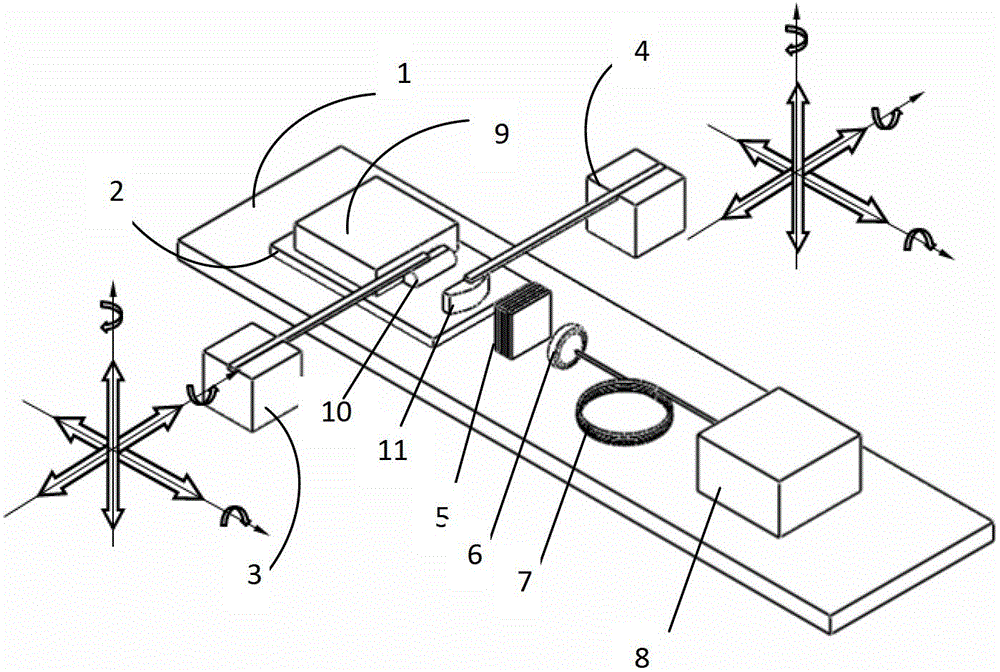
[0021] like figure 1 As shown, a method for adjusting a high-power semiconductor laser beam of the present invention is as follows

[0022] Step 1: turn on the semiconductor laser 9, the light beam emitted by the semiconductor laser 9 passes through the fast-axis collimating mirror 10 and the slow-axis collimating mirror 11 in sequence, and then enters the volume grating (VBG) 5;

[0023] Step 2: The laser light incident on the grating (VBG) 5 is introduced into the spectrometer 8 for spectral testing;

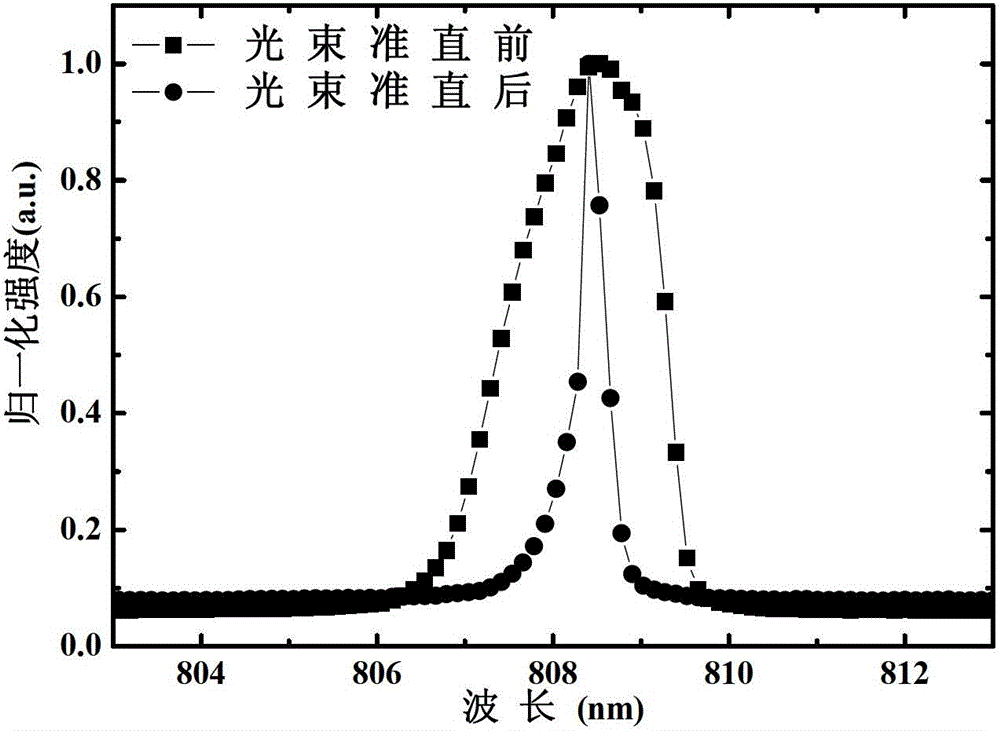
[0024] Step 3: Adjust the fast-axis collimating mirror 10 and the slow-axis collimating mirror 11 respectively until the spectrum measured by the spectrometer 8 is significantly narrowed, then the laser light emitted by the semiconductor laser 9 passes through the fast-axis collimating mirror 10 and the slow-axis collimating mirror 11. After the collimation lens 11 is c...


PUM


Abstract

The invention relates to a laser beam collimation adjusting method and a laser beam collimation adjusting device for a high-power semiconductor. The method comprises the following steps of lightening a semiconductor laser; enabling light beams emitted by each luminous point to pass through a fast-axis collimating mirror and a slow-axis collimating mirror in sequence respectively, and enter a volume Bragg grating (VBG); guiding laser light entering the VBG into a spectrometer for performing spectrum test; adjusting the fast-axis collimating mirror and the flow-axis collimating mirror respectively till a spectrum tested by using the spectrometer becomes narrower remarkably; enabling laser light emitted by the semiconductor laser to pass through a fast axis and a flow axis to become collimated ight beams; and fixing the positions of the fast-axis collimating mirror and the flow-axis collimating mirror. Due to the adoption of the laser beam collimation adjusting method and the laser beam collimation adjusting device, the high-precision collimation property of multiple paths of light beams can be adjusted in a compact space; and meanwhile, a spectrum narrowing signal is easy to identify, and whether a light path is collimated or not can be judged easily.

Description

technical field [0001] The invention belongs to the field of semiconductor lasers, and relates to a high-power semiconductor laser beam collimation adjustment method and device. Background technique [0002] At present, the fiber-coupled system of semiconductor lasers is developing in the direction of high output power and high brightness, and has been widely used in industrial, medical, military and other fields. In order to improve the high-power and high-brightness output of semiconductor lasers, it is usually realized by fiber coupling of multiple light-emitting points, that is, by first collimating multiple light-emitting points, and then passing the collimated multiple beams through a focusing lens. converged into a single fiber for output. In the process of collimating the propagation paths of multiple light-emitting points, two methods are usually used: The first method is to set a reference point on an expensive photodetector such as a CCD, and image the light-emit...

Claims


Application Information

Patent Timeline
Patent Type & Authority Patents(China)
IPC IPC(8): H01S5/06G02B27/30
Inventor 蔡万绍刘兴胜
Owner FOCUSLIGHT TECH
Learn More