Drive arrangement for a railcar and reversing gear

A drive device and transmission device technology, which is applied to the transmission device, transmission device, gear transmission device of a reciprocating piston internal combustion engine, etc., achieves the effects of balancing alignment errors, reducing manufacturing costs, and reducing costs

Inactive Publication Date: 2015-07-15
ZF FRIEDRICHSHAFEN AG
View PDF7 Cites 0 Cited by
  • Summary
  • Abstract
  • Description
  • Claims
  • Application Information

AI Technical Summary

Problems solved by technology

It may also be disadvantageous that the reversing drive is arranged on the vehicle axle

Method used


Image

  • Drive arrangement for a railcar and reversing gear
  • Drive arrangement for a railcar and reversing gear

Examples


Embodiment Construction

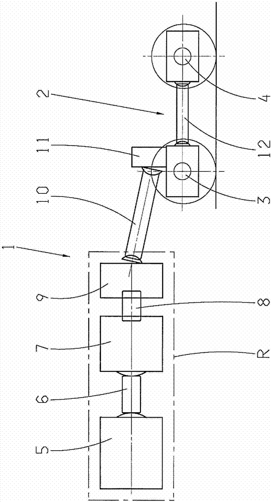
[0018] figure 1 A drive device 1 is shown for a motor rail vehicle (not shown), that is to say for a rail vehicle, which drive device is also referred to as a drive system. Seen in the direction of power flow, the drive device 1 comprises: a drive machine 5 designed as an internal combustion engine, preferably a diesel motor; a first cardan shaft 6; an automatic transmission 7; a clutch device 8; 10. Embodiments are also possible in which the drive machine 5 and the transmission 7 are directly flanged to one another, so that the cardan shaft 6 is omitted. The not-shown motor railcar has a frame, schematically indicated by a dot-dash rectangle R, and at least one bogie 2 . The drive assemblies 5 to 9 are arranged and fastened on or at the frame R. The bogie 2 is connected in a manner not shown to the vehicle frame R and carries the vehicle frame. The relative movement of the bogie 2 relative to the frame R is balanced by a second cardan shaft 10 , which drives the first veh...


PUM


Abstract

The invention relates to a drive arrangement for a railcar which has a vehicle chassis (R) and at least one bogie (2) comprising at least one drivable vehicle shaft (3, 4), the drive arrangement (1) comprising a driving machine (5) in the form of an internal combustion engine, a transmission (7), a reversing gear, at least one universal-joint shaft (6, 10) and a final drive (11), the driving machine (5) and the transmission (7) being disposed on the vehicle chassis (R) and the final drive (11) being disposed on the bogie (2). According to the invention, the reversing gear (9) is designed as an independent structural unit, disposed in the power flow direction behind the transmission (7), and secured on the chassis (R).

Description

technical field [0001] The present invention relates to a drive and a reversing drive for a motor rail vehicle known from DE 198 27 580 A1 of the applicant. Background technique [0002] DE 198 27 580 A1 by the applicant discloses a drive for a motor vehicle, in which a drive machine designed as an internal combustion engine drives the vehicle axle via a gearshift transmission, a cardan shaft and a reversing drive. The reversing gear is flanged as a separate structural unit to the axle gear (bevel gear) and is thus fastened to the axle or to the bogie carrying the axle of the vehicle. The reversing transmission has two coaxially arranged input gears connected by a clutch and switching device, one of which is driven to the driven shaft and the other input gear is also driven to the driven shaft (axle transmission bevel pinion). The axle gear and the upstream spur gear stages are also referred to as wheel set gears. [0003] The aforementioned reversing transmission is desc...

Claims


Application Information

Patent Timeline
Patent Type & Authority Patents(China)
IPC IPC(8): B61C9/12
CPCB61C9/12F16H3/14
Inventor 埃米尔·埃诺迪贝恩德·弗雷贝尔
Owner ZF FRIEDRICHSHAFEN AG
Why Eureka
Try Eureka