
Patrol inspection guidance system

A technology for guiding systems and subsystems, applied in the field of power system management, can solve problems such as high cost, high price, and non-compliance with the cost level, and achieve the effects of long life, fast processing, and accident avoidance

Active Publication Date: 2013-04-24
BEIJING GUODIANTONG NETWORK TECH CO LTD +1
View PDF4 Cites 8 Cited by
  • Summary
  • Abstract
  • Description
  • Claims
  • Application Information

AI Technical Summary

Problems solved by technology

[0004] However, in the prior art, 3 to 4 base stations need to be deployed in each monitoring area of ​​the substation area, and the overall cost is relatively high. In addition, the prior art needs to use active RFID tags, and the price is relatively high. Therefore, in the prior art The patrol inspection and guidance system does not meet the cost level required by the new generation of smart substations

Method used


Image

  • Patrol inspection guidance system
  • Patrol inspection guidance system
  • Patrol inspection guidance system

Examples


Embodiment 1

[0064] figure 1 It is a structural diagram of an inspection guidance system disclosed in Embodiment 1 of the present invention. Such as figure 1 As shown, the system includes:

[0065] Positioning subsystem 101, background control subsystem 102 and linkage subsystem 103;

[0066] The positioning subsystem 101 is used to read the radio frequency identification (Radio Frequency Identification, RFID) information of the inspector, and send the RFID information to the background control subsystem 102;

[0067] Specifically, the positioning subsystem 101 can be installed above the doors at the entrances of different areas of the substation, or installed above different cabinets in the same area of ​​the substation. When the inspector passes the entrances of different areas of the substation and enters the area, the positioning subsystem 101 installed above the entrance door will read the RFID information of the inspector, or, the distance between the inspector and the cabinet Wh...

Embodiment 2

[0098] Figure 5 It is a structural diagram of another inspection and guidance system disclosed in Embodiment 2 of the present invention. Such as Figure 5 As shown, the system includes:

[0099] Positioning subsystem 501, background control subsystem 502, linkage subsystem 503 and monitoring subsystem 504;

[0100] The positioning subsystem 501 is used to read the RFID information of the inspector, and send the RFID information to the background control subsystem 502;

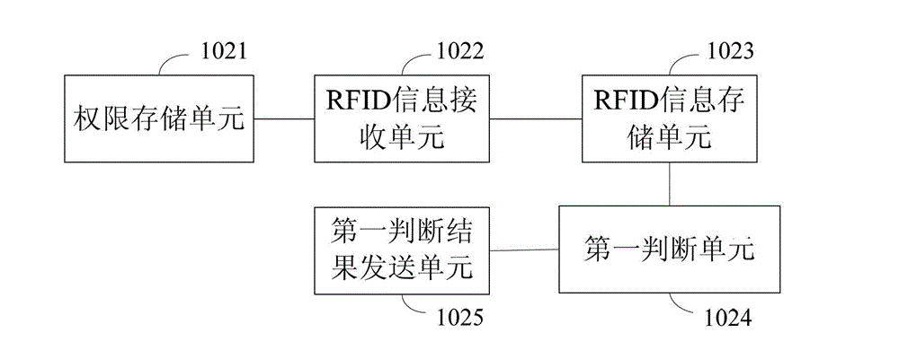
[0101] The background control subsystem 502 is used to store the access rights of different areas of the substation or the access rights of different cabinets in the same area, receive the RFID information, store the RFID information, and judge whether the inspector has access rights, sending the first judgment result to the linkage control subsystem 503, and sending the RFID information and the first judgment result to the monitoring subsystem 504;

[0102] The linkage control subsystem 503 is used to con...


PUM


Abstract

The invention discloses a patrol inspection guidance system. The patrol inspection guidance system comprises a positioning subsystem, a background control subsystem and a linkage subsystem. The positioning subsystem is used for reading radio frequency identification (RFID) information of a patrol inspector and sending the RFID information to the background control subsystem. The background control subsystem is used for storing access permissions of different areas of a transformer substation or access permissions of different equipment cabinets of the same area, receiving the RFID information, storing the RFID information, judging whether the patrol inspector has the access permissions according to the RFID information, and sending a first judgment result to the linkage control subsystem. The linkage control subsystem is used for starting a linkage device according to the first judgment result to guide the patrol inspector to work. According to the patrol inspection guidance system, RFID positioning by using of a base station can be avoided, cost is reduced, and a construction cost level required by a new generation of intelligent transformer substations can be met.

Description

technical field [0001] The invention relates to the field of power system management, in particular to a patrol inspection and guidance system. Background technique [0002] In today's society, electricity is used as the main power in daily production and life. With more and more large-scale substations, the safety management of substations has become an important task of power system management. If the management is not in place, accidents are prone to occur. Therefore, it is necessary to arrange inspection personnel to inspect the substation. [0003] In the existing technology, 3 to 4 base stations are deployed in each area that needs to be monitored in the substation, and a positioning sensor network is installed. All sensors are connected through standard Ethernet, and inspectors carrying active RFID tags will be detected by the sensors after entering the monitoring area. Capture, through the interaction between the base station and the sensor information, the position...

Claims


Application Information

Patent Timeline
IPC IPC(8): G06K17/00G06Q10/06G06Q50/06
Inventor 王春新李栋华王焕娟杨友朋李朝峰张竞文刘亚坤李凡夏升谢斌田祥花
Owner BEIJING GUODIANTONG NETWORK TECH CO LTD
Learn More