
Test bed for hydraulic oil pumping device

A technology of pumping units and test benches, which is applied to the testing of machines/structural components, measuring devices, instruments, etc., can solve problems such as unrealistic and impossible oil well detection by manufacturers, and achieve the effect of reducing production costs

Inactive Publication Date: 2013-04-24
无锡市科优液压设备制造有限公司
View PDF7 Cites 5 Cited by
  • Summary
  • Abstract
  • Description
  • Claims
  • Application Information

AI Technical Summary

Problems solved by technology

[0002] The hydraulic pumping unit test bench is generally used by the pumping unit manufacturer. After the pumping unit is manufactured, it needs to be inspected and accepted at the factory, and a certificate of conformity will be issued. During the testing process, its operating performance is the main indicator, which requires an oil well device to Detect the main working parameters of the pumping unit to see if they meet the design targets. Because the pumping unit is used in large oil wells, it is impossible for manufacturers to use oil wells for testing, and the actual cost of an oil well is several million, and some tens of millions , so it is unrealistic to use oil well test to detect, the above problems need to be solved

Method used


Image

  • Test bed for hydraulic oil pumping device

Examples


Embodiment Construction

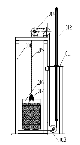
[0009] The hydraulic pumping unit test bench includes a frame 001, the frame 001 is a rectangular frame structure, a hydraulic cylinder mounting seat 011 is fixedly connected to one side of the frame 001, and a hydraulic cylinder is vertically arranged in the hydraulic cylinder mounting seat 011 012, the piston rod of the hydraulic cylinder 012 extends downwards into the cavity of the hydraulic cylinder mounting seat 011, and a direction-changing pulley 013 is fixedly connected to the frame 001 near the bottom of the cavity of the hydraulic cylinder mounting seat 011, and the frame The top of 001 is provided with a pulley block 014, and one end of the piston rod of the hydraulic cylinder 012 extending into the cavity of the hydraulic cylinder mounting seat 011 is connected with a steel wire rope 015. The load-bearing basket 016 in the framework of the frame 001 is connected, and a load-bearing code 017 is arranged in the load-bearing basket 016. The pulley block 014 is a plural...


PUM


Abstract

The invention provides a test bed for a hydraulic oil pumping device, and relates to auxiliary equipment used for the oil pumping device. The test bed for the hydraulic oil pumping device comprises a machine frame. The machine frame is in a rectangular frame structure, a hydraulic cylinder installation base is fixedly connected with one side of the machine frame, and a hydraulic cylinder is vertically arranged in the hydraulic cylinder installation base. A piston rod of the hydraulic cylinder extends downward into a cavity of the hydraulic cylinder installation base, a turning pulley is arranged near the bottom of the cavity of the hydraulic cylinder installation base and is fixedly connected with the machine frame, and a pulley block is arranged at the top end of the machine frame. A steel wire rope is connected with the end, extending into the cavity of the hydraulic cylinder installation base, of the piston rod of the hydraulic cylinder, and the steel wire rope is anticlockwise winded on the turning pulley and the pulley block, and the tail end of the steel wire rope is connected with a loading basket which is arranged in a frame of the machine frame. Loading weight is arranged in the loading basket, manufacture cost of the test bed is effectively reduced, and various loads and wells with different depths can be simulated. An oil cylinder and a main machine can be tested simultaneously or independently, and indoor operation can be carried out in a workshop with normal height.

Description

technical field [0001] The invention relates to an auxiliary equipment for a pumping unit, in particular to a test bench for a hydraulic pumping unit. Background technique [0002] The hydraulic pumping unit test bench is generally used by the pumping unit manufacturer. After the pumping unit is manufactured, it needs to be inspected and accepted at the factory, and a certificate of conformity will be issued. During the testing process, its operating performance is the main indicator, which requires an oil well device to Detect the main working parameters of the pumping unit to see if they meet the design targets. Because the pumping unit is used in large oil wells, it is impossible for manufacturers to use oil wells for testing, and the actual cost of an oil well is several million, and some tens of millions , so it is unrealistic to use oil well test to detect, and the above problems need to be solved. Contents of the invention [0003] Aiming at the deficiencies of the...

Claims


Application Information

Patent Timeline
IPC IPC(8): G01M99/00
Inventor 钱雪强邵建辉周幼海
Owner 无锡市科优液压设备制造有限公司
Learn More