
Terminating device system

A termination and device technology, applied in the field of termination device systems, can solve the problems of power waste, resistance consumption power consumption, etc., and achieve the effect of reducing power consumption and saving energy

Active Publication Date: 2013-04-17
MONTAGE TECHNOLOGY CO LTD
View PDF3 Cites 0 Cited by
  • Summary
  • Abstract
  • Description
  • Claims
  • Application Information

AI Technical Summary

Problems solved by technology

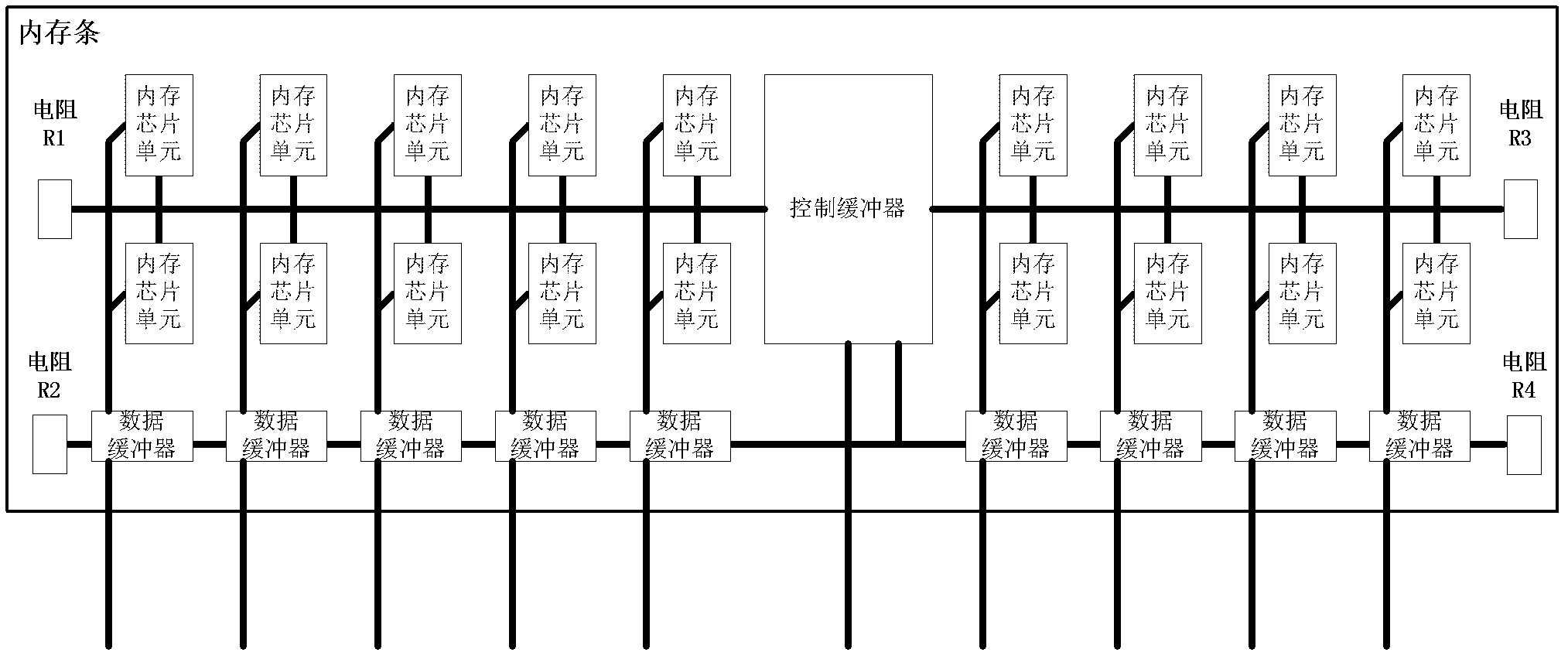
The biggest problem of the memory stick with this circuit structure is: when the memory chip unit and the data buffer are in an idle state, since the control buffer will still output a digital signal of 1 or 0, the resistor connected to it will consume power. cause waste of electric energy, therefore, it is urgent to improve the structure of this type of circuit

Method used


Image

  • Terminating device system
  • Terminating device system
  • Terminating device system

Examples


Embodiment Construction

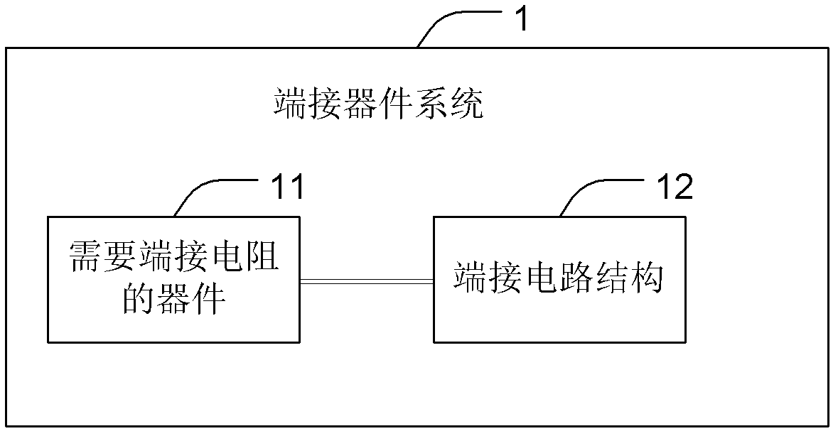
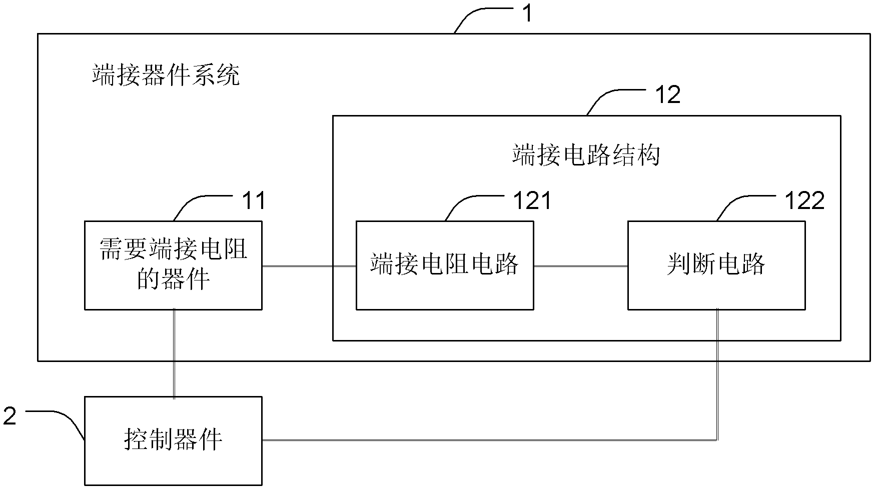
[0026] see figure 2 , The termination device system 1 of the present invention includes a device 11 requiring a termination resistance and a termination circuit structure 12 .

[0027] The device 11 that needs a termination resistance includes any component that needs a termination resistance during operation, preferably, including but not limited to a memory chip unit, a data buffer, etc., for example, a register buffer dual in-line memory bank ( RDIMM) or Load Reduced Dual Inline Memory (LRDIMM) memory chip units and / or data buffers etc.

[0028] The termination circuit structure 12 includes any one that can provide a termination resistance to the device 11 that requires a termination resistance when the device 11 that requires a termination resistance is in operation, and when the device 11 that requires a termination resistance When idle, no termination resistor circuit is provided to the device 11 that needs a termination resistor.

[0029] Preferably, the termination ...


PUM


Abstract

The invention provides a terminating device system which comprises a device needing terminating a resistor and a terminating circuit structure, wherein the terminating circuit structure comprises a terminating resistor circuit and a judging circuit connected with the terminating resistor circuit; the terminating resistor circuit comprises at least one controlled terminating unit, each controlled terminating unit comprises a terminating connecting end used for being connected with the device needing terminating the resistor, a controlled switch and a resistor, and each controlled terminating unit is used for providing the terminating resistor to the device connected with the terminating connecting end on the basis of switching-on or off of the controlled switch; and the judging circuit is used for judging whether the device is needed to be connected with the terminating resistor or not on the basis of control commands of control devices of the devices connected to the terminating connecting ends so as to output switching-on or off control signals to the controlled switches of the terminating resistor circuit to control the switching-on or off, therefore, the terminating resistor is provided on the basis of the requirement of the device, and then the waste of power consumption of the device in an idle state can be avoided.

Description

technical field [0001] The invention relates to the field of circuits, in particular to a terminal device system. Background technique [0002] For various existing devices that require termination resistors, for example, memory chip units of DDR memory, data buffers, etc., termination resistors are often required during use, such as figure 1 As shown, the left end of the plurality of memory chips included in the memory stick is connected to a resistor R1, the right end is connected to a resistor R3, the left end of the data buffer is connected to a resistor R2, and the right end is connected to a resistor R4. The biggest problem of the memory stick with this circuit structure is: when the memory chip unit and the data buffer are in an idle state, since the control buffer will still output a digital signal of 1 or 0, the resistor connected to it will consume power. Causes the waste of electric energy, therefore, urgently needs to improve this kind of circuit structure. Co...

Claims


Application Information

Patent Timeline
Patent Type & Authority Applications(China)
IPC IPC(8): G11C11/4096
CPCH03K19/0005
Inventor 李春一马青江
Owner MONTAGE TECHNOLOGY CO LTD
Learn More