
A small current clamp for on-site calibration of live measurement

A field calibration, current clamp technology, applied in the measurement of current/voltage, measurement of electrical variables, measurement devices, etc., can solve the problems of small operation space, inconvenient operators, irregularities, etc., to reduce the cross-sectional area of ​​the magnetic circuit, The effect of ensuring measurement accuracy

Active Publication Date: 2015-12-02
SHANGHAI MUNICIPAL ELECTRIC POWER CO +1
View PDF6 Cites 0 Cited by
  • Summary
  • Abstract
  • Description
  • Claims
  • Application Information

AI Technical Summary

Problems solved by technology

[0003] However, in the process of practical application, we found that because the actual site conditions of live measurement sites vary widely, and the installation arc of the current circuit of the current circuit of the equipment to be tested-such as the electric energy meter and other devices is small and irregular, while the existing technology The size of the current clamp is relatively large. Due to the small operating space, the existing current clamp cannot penetrate the current wire during the operation, which brings inconvenience to the on-site operators. accidents, endangering the safety of the power grid, and even causing casualties in severe cases

Method used


Image

  • A small current clamp for on-site calibration of live measurement
  • A small current clamp for on-site calibration of live measurement
  • A small current clamp for on-site calibration of live measurement

Examples


Embodiment

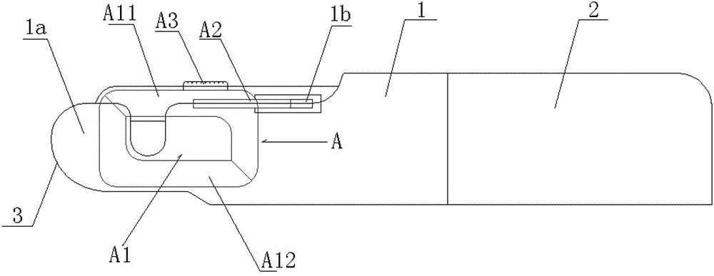
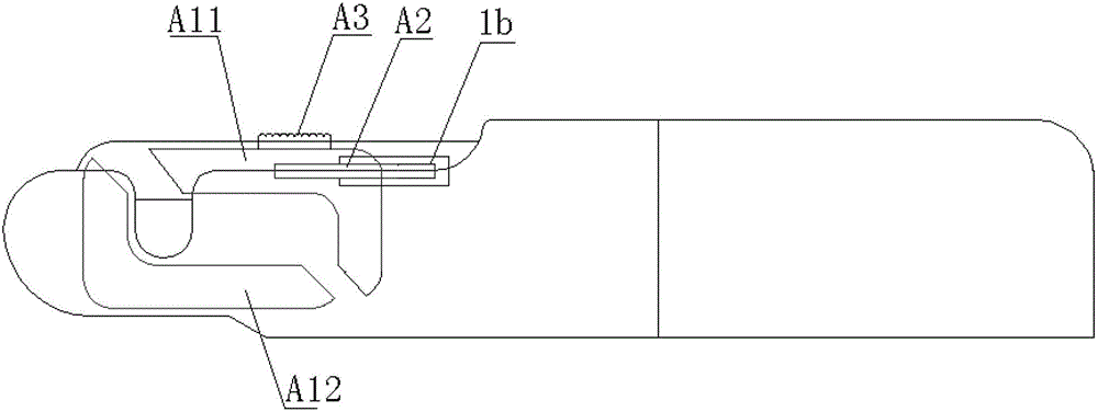
[0023] Such as figure 1 , figure 2 and image 3 As shown, a small-sized current clamp is used for on-site calibration of live measurement. One end of the current clamp body 1 is arranged in the clamp body jacket 2, and the other end of the current clamp body extends out of the clamp body jacket. The protruding current clamp body A clamp body potting 3 is provided at the clamp head 1a;

[0024] The middle part of the protruding end of the current clamp body 1 is provided with a body slideway 1b in the same direction as the body;

[0025] The inside of the current clamp head 1a is provided with a measuring magnetic core assembly A that can move left and right along the slideway of the clamp body.

[0026] The small current clamp used for on-site verification of live measurement of the present invention changes the winding space position of the secondary winding wound on the current clamp magnetic core (magnetic circuit) in the prior art, and changes the working position of t...


PUM


Abstract

The invention provides a small type current clamp for the checking of a live line measurement scene, wherein one end of a current clamp body is arranged in a clamp body jacket; the other end of the current clamp body stretches out of the clamp body jacket; a clamp body embedment is arranged at an out-stretching current clamp head; a clamp body sliding chute in the same direction with a clamp body is formed in the middle part of an out-stretching end of the current clamp body; the interior of the current clamp head is provided with a measurement magnetic core component which can move left and right along the clamp body sliding chute; and a dynamic magnetic arm and a static magnetic arm of the component are closed to form a closed magnetic circuit and are opened to cause the whole closed magnetic circuit to be disconnected. With the adoption of the small type current clamp for the checking of the live line measurement scene, the problem that due to large volume, the current clamp of the prior art is inapplicable for small operation space is solved; moreover, the working position of the measurement magnetic core component extends to the current clamp head from the interior of the current clamp body; in such a way, the length of a magnetic path in the current clamp body is decreased; under the premise of guaranteeing a proportion between the cross section of the magnetic path and the magnetic path length, the measurement precision of the current clamp is guaranteed; and therefore, the small type current clamp for the checking of the live line measurement scene is applicable for the field of various live line measurements.

Description

technical field [0001] The invention relates to a device for electric power measurement, in particular to a current clamp applied to the field of on-site calibration of live measurement. Background technique [0002] At present, a current clamp is widely used in the field of live measurement field calibration, and the current clamp is a current transformer with the characteristics of opening and closing magnetic circuits. On the premise of not dismantling the current loop in the live measurement site, by opening the magnetic circuit of the current clamp, the measured current line can be wrapped in the magnetic loop of the current clamp, and after closing the magnetic circuit of the current clamp, a detection The current transformer of the current loop current cooperates with related instruments to detect electrical parameters such as current, power, and electric energy. [0003] However, in the process of practical application, we found that because the actual site conditio...

Claims


Application Information

Patent Timeline
Patent Type & Authority Patents(China)
IPC IPC(8): G01R19/00
Inventor 朱立辉余慧赟叶铮马振皎
Owner SHANGHAI MUNICIPAL ELECTRIC POWER CO
Learn More