
Gas rotary joint

A technology of rotary joints and inflatable joints, applied in the direction of pipe elements, etc., can solve problems such as the inability to ensure that the inflating path and the vacuuming path are parallel and evenly surrounding the rotating mechanism, leakage, lack of inflatable and vacuuming fusion, etc., to achieve enhanced sealing The effect of stability, simple connection and easy maintenance

Inactive Publication Date: 2015-09-09
杭州安杰诺智能机械有限公司
View PDF8 Cites 2 Cited by
  • Summary
  • Abstract
  • Description
  • Claims
  • Application Information

AI Technical Summary

Problems solved by technology

[0003] The present invention is mainly aimed at the existing rotating mechanism that needs to be inflated and vacuumed at the same time, does not have the ability to integrate the inflation and vacuum on the same joint, and cannot ensure that the inflation path and the vacuum path can be parallel and uniform around the rotation mechanism Axis and other issues, provide a gas that can connect the inflator and vacuum pump at the same time, ensure that the inflation path and the vacuum path are parallel and uniform around the rotation axis, do not affect the normal rotation, have high sealing performance, and avoid mutual leakage of inflation and vacuum. with swivel joint

Method used


Image

  • Gas rotary joint
  • Gas rotary joint

Examples


Embodiment 1

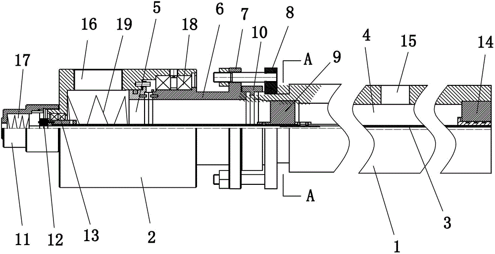
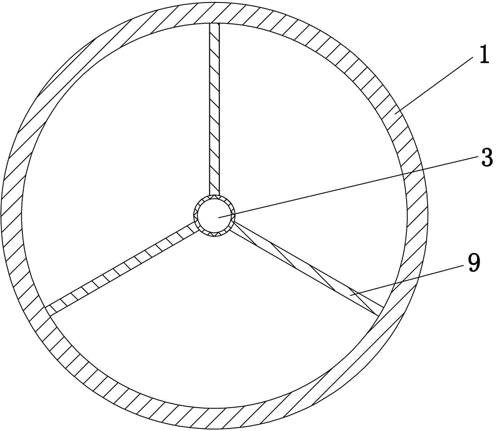
[0019] Embodiment 1: as figure 1 , 2 As shown, a gas rotary joint includes a rotary main shaft 1 and a joint main body 2, and the rotary main shaft 1 and the joint main body 2 are located on the same axis. The interior of the rotating spindle 1 is hollow with a first vacuum chamber 4, the joint body 2 includes a shell, and the inside of the shell has a second vacuum chamber 5, and a vacuum interface 16 is opened on the joint body 2, and the vacuum joint 16 is connected to the inside of the joint body 2. The second vacuum chamber 5 is connected; a vacuum outlet 15 is opened on the rotating main shaft 1 , and the vacuum outlet 15 is connected to the first vacuum chamber 4 inside the rotating main shaft 1 . A fixed connecting sleeve 6 is installed at one end of the joint body 2 close to the rotating main shaft 1, and the end of the fixed connecting sleeve 6 away from the rotating main shaft 1 is located inside the joint main body 2, and the fixed connecting sleeve 6 is connected...


PUM


Abstract

The invention relates to a connecting component, particularly to a pneumatic rotary joint. The pneumatic rotary joint comprises a rotary spindle, a joint body is coaxially connected at one end of the rotary spindle, a first vacuum gas chamber is arranged in the rotary spindle, a second vacuum gas chamber is arranged in the joint body and communicated with the first vacuum gas chamber, the rotary spindle is provided with a vacuum outlet communicated with the first vacuum gas chamber, the joint body is provided with a vacuum port communicated with the second vacuum gas chamber, an inflation spindle pipe is arranged at the axis position of the rotary spindle and the joint body, the first vacuum gas chamber and the second vacuum gas chamber evenly surround the inflation spindle pipe, and an inflation connection is fixedly arranged at one end far away from the rotary spindle on the joint body and communicated with the inflation spindle pipe. The pneumatic rotary joint has the advantages of being high in tightness, capable of guaranteeing an inflation path and a vacuum pumping path to be parallel and to surround the rotation axis evenly and the like.

Description

technical field [0001] The invention relates to a connecting part, in particular to a rotary joint for gas. Background technique [0002] The existing rotary mechanism needs to inflate the interior of the rotary mechanism and vacuumize it at the same time, but there is no assembly connector in the prior art, only the inflator and the vacuum pump can be connected to the rotary mechanism, and they must be connected to the rotary mechanism. Different positions easily affect the rotation of the rotating mechanism, and it cannot be guaranteed that the inflation path and the vacuuming path can be parallel and uniform around the axis of the rotating mechanism. Moreover, this connection is complicated and inconvenient for maintenance, repair and replacement. The two passages of inflation and vacuuming require high sealing performance, not only can there be no air leakage, but also the sealing and no leakage between the two passages should be ensured. Some joints are only suitable ...

Claims


Application Information

Patent Timeline
Patent Type & Authority Patents(China)
IPC IPC(8): F16L39/06
Inventor 张德祥胡志坚
Owner 杭州安杰诺智能机械有限公司
Learn More