
Anaerobic reactor

An anaerobic reactor and tank body technology, applied in the field of anaerobic reactors, can solve the problems of small sludge volume load, high concentration of suspended solids in the effluent, and low processing capacity, and achieve uniform water distribution and low concentration of suspended solids in the effluent , the effect of strong processing ability

Inactive Publication Date: 2013-04-17
XIAMEN RESINTECH ENVIRONMENT PROTECTION PROJECT
View PDF11 Cites 0 Cited by
  • Summary
  • Abstract
  • Description
  • Claims
  • Application Information

AI Technical Summary

Problems solved by technology

[0004] The purpose of the present invention is to provide a new type of water treatment system for the shortcomings of the prior art, such as uneven distribution of influent and effluent water, anaerobic sludge deposition tank bottom and sludge volume load, low treatment capacity, and high concentration of suspended solids in effluent water. Anaerobic reactor

Method used


Image

  • Anaerobic reactor
  • Anaerobic reactor
  • Anaerobic reactor

Examples


Embodiment Construction

[0020] The present invention will be further described in detail below in conjunction with the embodiments and the accompanying drawings, but the embodiments of the present invention are not limited thereto.

[0021] The main purpose of the conception of the present invention is to solve the problem of inhomogeneous distribution of influent and effluent water, anaerobic sludge deposition at the bottom of the tank and sludge in the prior art, which only exist to filter sewage through baffles and anaerobic fillers. The disadvantages of small volume load, low processing capacity, and high concentration of suspended solids in the effluent. The present invention solves the above-mentioned problems by adding a water distribution plate and a mud discharge pipe on one side of the water drop partition.

[0022] Such as Figure 2-4 Shown, specifically, the technical scheme that the present invention adopts is to provide a kind of anaerobic reactor, and it comprises tank body 11, anaero...


PUM


Abstract

The invention discloses an anaerobic reactor which comprises a tank body, anaerobic fillers and a water inlet pipe and a water outlet pipe which are mounted at the two ends of the tank body respectively, wherein a drop clapboard is further arranged in the tank body; a water distribution board is further arranged in the tank body adjacent to one end of the water outlet pipe on one side of the drop clapboard; the anaerobic fillers are on the water distribution board which is not as high as the drop clapboard; and a sludge pipe is further arranged on the tank body adjacent to one end of the water outlet pipe at the lower end of the water distribution board. The anaerobic reactor has the advantages that the water inlet, outlet and distribution are uniform, the anaerobic sludge deposited is easy to discharge, the volume loading of sludge is large, the treatment capacity is high and the concentration of effluent suspended matters is low.

Description

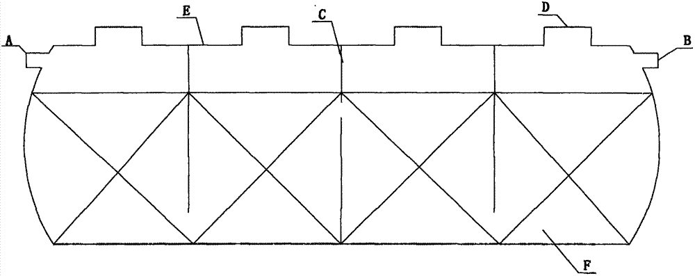
technical field [0001] The invention relates to the technical field of sewage, in particular to an anaerobic reactor. Background technique [0002] There are many types of buried sewage biological treatment equipment. According to different microbial principles, structures and materials, they mainly include the following categories: reinforced concrete septic tanks, such as patents 200920100115.2, 201120300347.X and 200520081018.5, etc., glass tempered Septic tanks, such as patents 200920101361.X, 99215994.6, 200820148736.3, 201120270489.6, etc., and carbon steel buried anaerobic tanks. The structure of the commonly used unpowered septic tank is similar to that of the traditional reinforced concrete septic tank. The structure is relatively simple, and the water flow path is in a state of up and down deflection. [0003] Sewage treatment equipment of the prior art, such as figure 1 In the glass fiber reinforced plastic septic tank shown, the sewage enters the tank body E th...

Claims


Application Information

Patent Timeline
Patent Type & Authority Applications(China)
IPC IPC(8): C02F3/28
Inventor 张文钦
Owner XIAMEN RESINTECH ENVIRONMENT PROTECTION PROJECT
Learn More