
Hob mounting structure

A mounting structure and hob technology, which is applied in the direction of milling cutters, metal processing equipment, milling machine equipment, etc., can solve the problem of inability to eliminate the gap between the inner hole of the hob and the mandrel, the cumulative error of the chip flute, and the failure to use Requirements and other issues, to meet the accuracy, reduce tooth profile error, and ensure the effect of sharpening quality

Inactive Publication Date: 2013-04-17
归杏花
View PDF0 Cites 6 Cited by
  • Summary
  • Abstract
  • Description
  • Claims
  • Application Information

AI Technical Summary

Problems solved by technology

[0002] The existing hob is generally clamped by the cylindrical mandrel. Because there is a fit gap between the inner hole of the hob and the mandrel, there is a reference position error. Due to the existence of the reference position error, it will inevitably affect the The accumulative error of the pitch of the chip flute after the hob is sharpened. Most of the hobs currently available on the market have low inner hole accuracy. In addition, after a period of use, the inner hole wears out, and many hobs have out-of-tolerance hole diameters. The shaft cannot eliminate the fit gap between the inner hole of the hob and the mandrel, so that the tooth profile of the gear rolled out by some hobs is out of tolerance, which cannot meet the required use requirements

Method used


Image

  • Hob mounting structure

Examples


Embodiment Construction

[0010] The present invention is described below in conjunction with accompanying drawing.

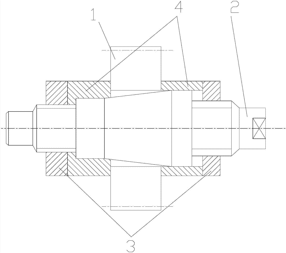
[0011] attached figure 1 It is a hob installation structure according to the present invention, which includes a hob 1 and a tapered mandrel 2; the inner hole of the hob 1 is installed on the tapered mandrel 2; The tapered mandrel 2 is fixed; a positioning pad 4 is also provided between the hob 1 and the nut 3 .

[0012] When using the improved tapered mandrel 2 to clamp the hob 1, first install the hob 1 into the conical surface of the tapered mandrel 2, push it tightly by hand, turn the right end nut 3, and push the right positioning pad 4 and The right end of the hob 1 is in contact, then the nut 3 on the left is turned, and the positioning pad 4 at the left end is pushed to press the hob 1 tightly.

[0013] The solution of the present invention uses the tapered mandrel 2 to position the inner hole of the hob 1 to eliminate the fit gap between the inner hole of the hob 1 and the ta...


PUM


Abstract

The invention discloses a hob mounting structure which comprises a hob and a conical mandrel. A hob inner hole is arranged on the conical mandrel. The conical mandrel is fixed by the hob through nuts. Positioning wafers are further arranged between the hob and the nuts. The hob inner hole of the conical mandrel is positioned, so that a fit clearance butane the hob inner hole and the conical mandrel is eliminated. The conical mandrel is highly tapered and prevents the hob from being tilted during clamping. The hob is axially positioned through the positioning wafers at two ends of the conical mandrel. Therefore, accumulative pitch errors of a chip pocket caused by the clearance are basically eliminated. Cutter sharpening precision of a front tool surface of the hob is increased, cutter sharpening quality is guaranteed, and accordingly tooth profile errors in gears are decreased. Machined products are stable in stability, with the precision meeting the design requirement.

Description

technical field [0001] The invention relates to a hob installation structure and belongs to the technical field of mechanical clamping. Background technique [0002] The existing hob is generally clamped by the cylindrical mandrel. Because there is a fit gap between the inner hole of the hob and the mandrel, there is a reference position error. Due to the existence of the reference position error, it will inevitably affect the The accumulative error of the pitch of the chip flute after the hob is sharpened. Most of the hobs currently available on the market have low inner hole accuracy. In addition, after a period of use, the inner hole wears out, and many hobs have out-of-tolerance hole diameters. The shaft cannot eliminate the fit gap between the inner hole of the hob and the mandrel, so that the tooth profile of the gear rolled out by some hobs is out of tolerance, which cannot meet the required use requirements. Contents of the invention [0003] In view of the above ...

Claims


Application Information

Patent Timeline
IPC IPC(8): B24B3/12
Inventor 归杏花
Owner 归杏花
Learn More