
Suspending method capable of preventing suspending plate from shaking

A technology for ceiling panels and ceilings, applied in the direction of ceilings, building components, buildings, etc., can solve the problems of matching clearance, inconvenient maintenance and disassembly, and shaking of ceiling panels, and achieve the effect of eliminating matching clearance, ensuring synchronization, and ensuring stability.

Active Publication Date: 2020-04-28
成都劲启家居有限公司
View PDF6 Cites 2 Cited by
  • Summary
  • Abstract
  • Description
  • Claims
  • Application Information

AI Technical Summary

Problems solved by technology

[0005] The purpose of the present invention is to provide a ceiling method for preventing the ceiling from shaking, which solves the problem that in the existing ceiling installation method, there is a fit gap, which causes the ceiling to shake, has poor stability, or is too tight to facilitate later maintenance and disassembly. question

Method used


Image

  • Suspending method capable of preventing suspending plate from shaking
  • Suspending method capable of preventing suspending plate from shaking
  • Suspending method capable of preventing suspending plate from shaking

Examples


Embodiment 1

[0038] A ceiling suspension method for preventing ceiling boards from shaking, comprising the steps of:

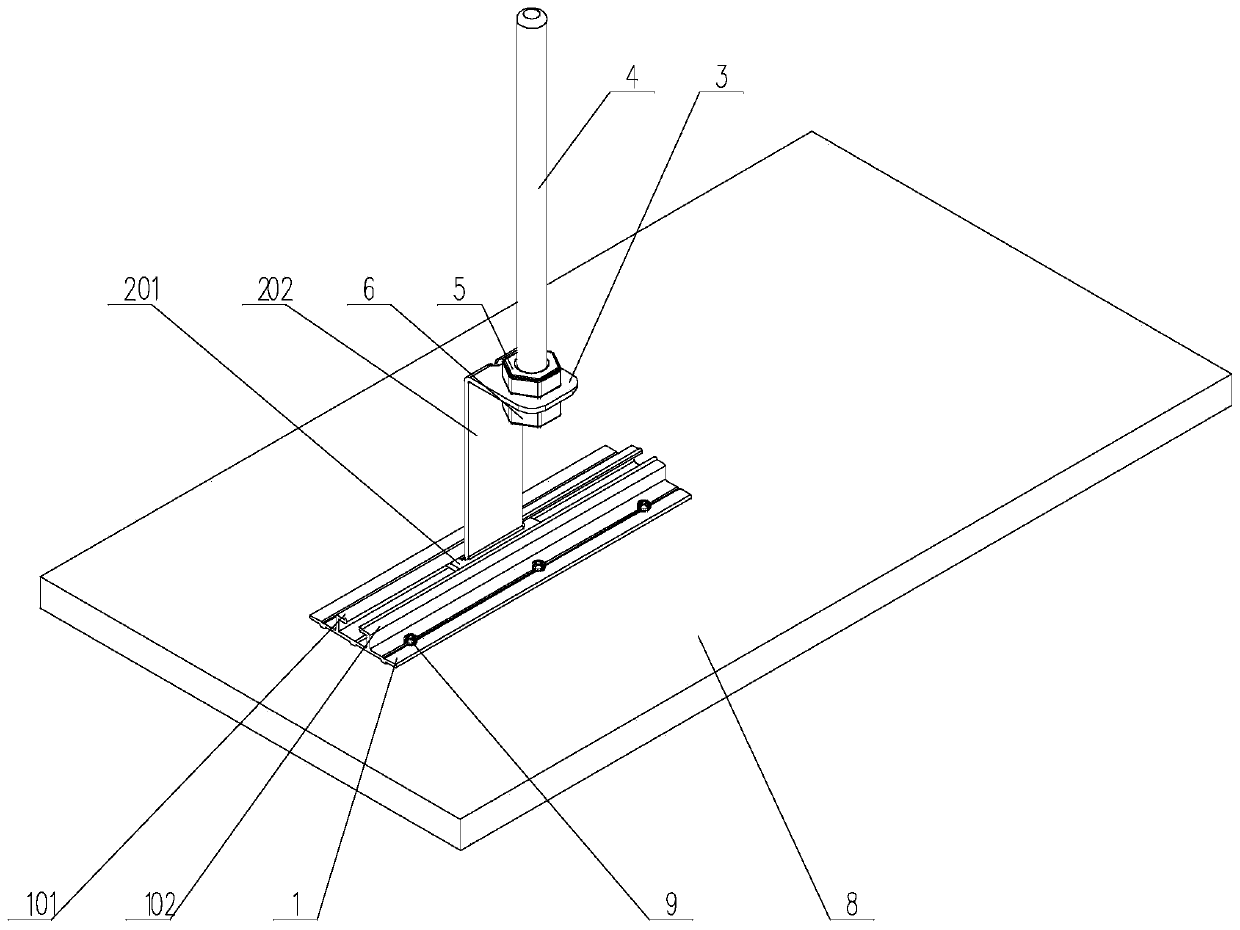
[0039] S1, the positioning board 1 is fixed on the upper surface of the ceiling board 8, such as image 3 shown;

[0040] S2. Place the clamping plate 2 on one side of the positioning plate 1, and make it be located between the left slat 101 and the right slat 102;

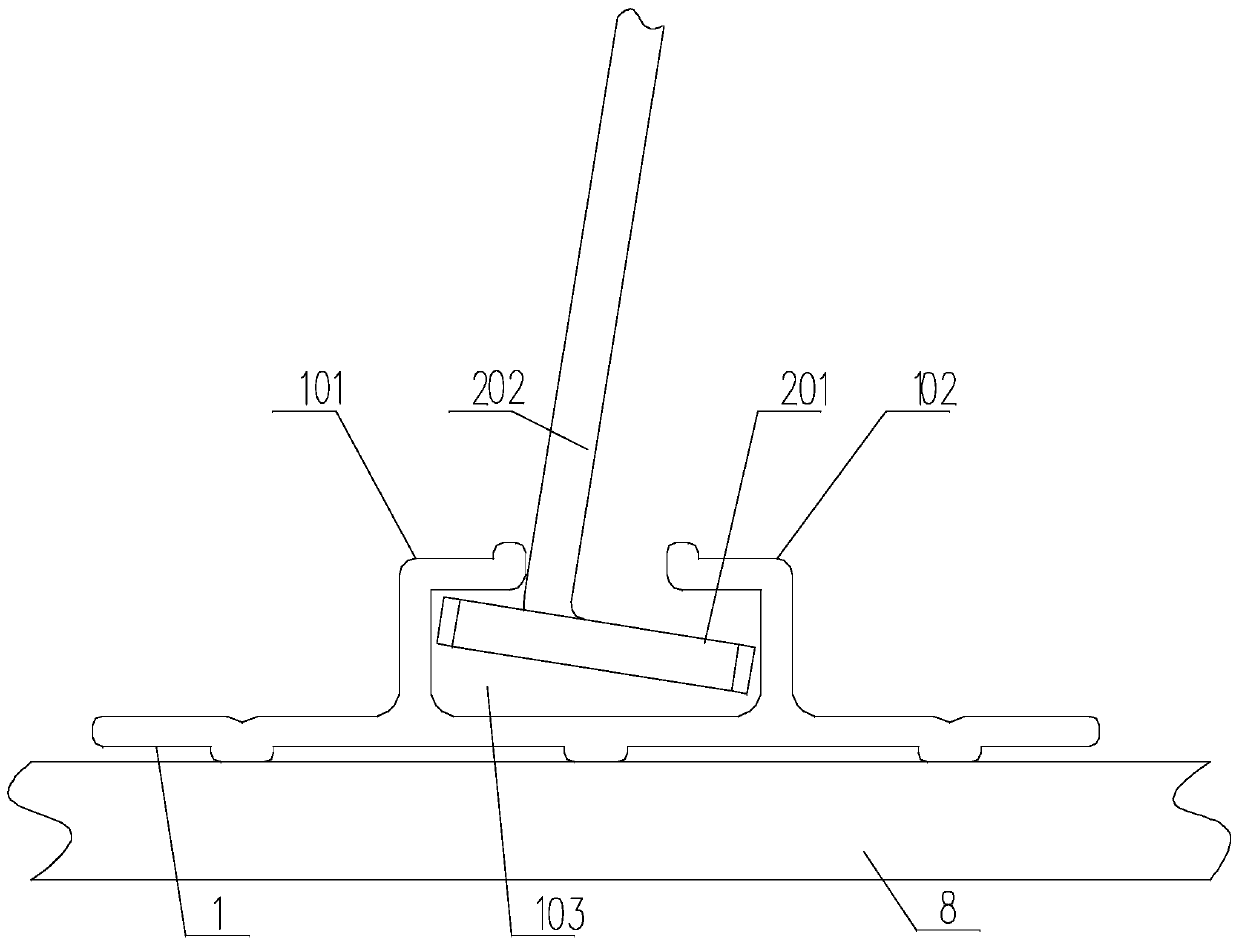
[0041] S3. Turn the clamping plate 2 so that the end of the horizontal plate B201 away from the vertical plate B202 is inclined downward, as figure 1 shown;

[0042] S4, insert the clamping plate 2 into the installation through groove 103;

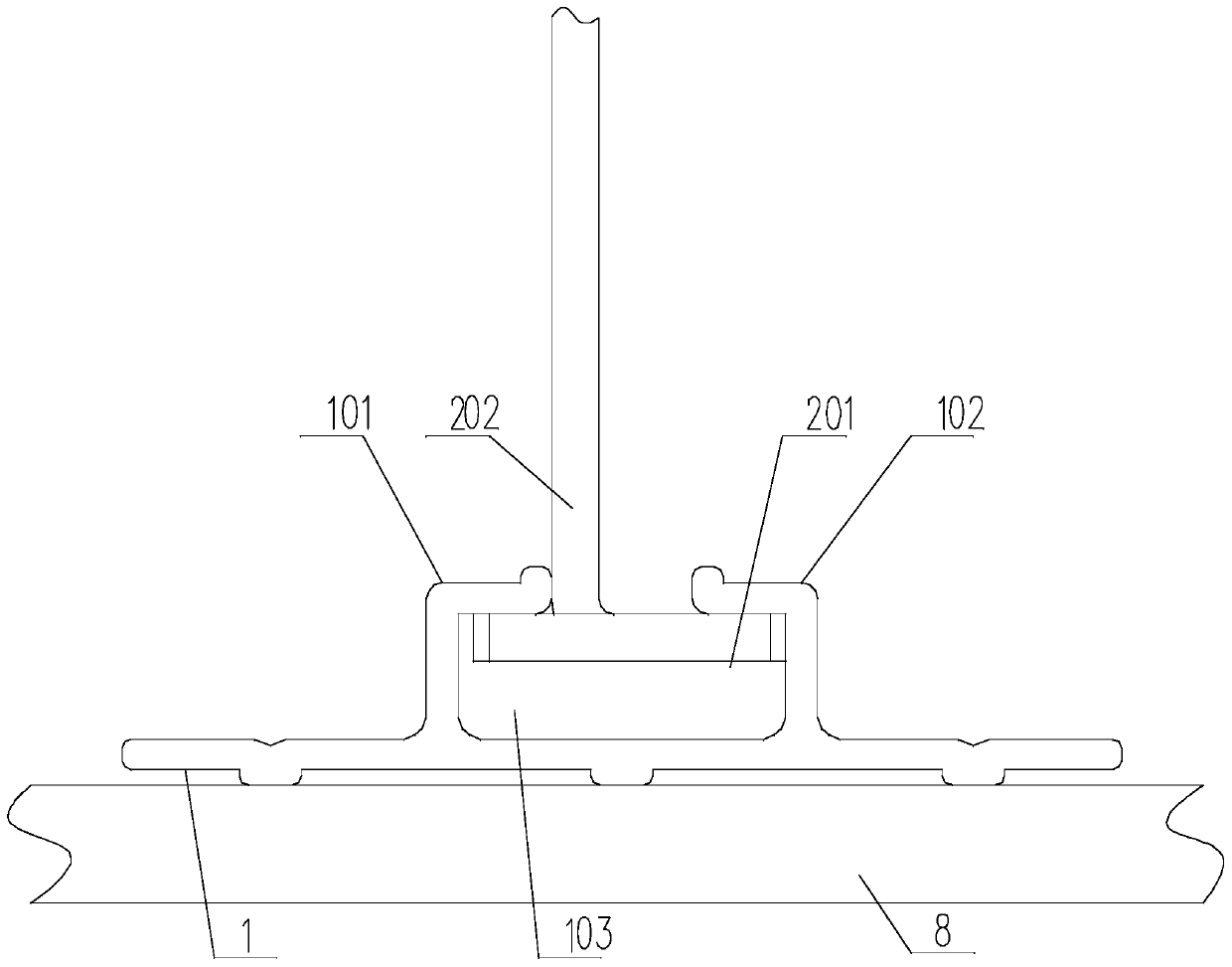
[0043] S5. Reversely rotate the clamping plate 2 so that the horizontal plate B201 is parallel to the positioning plate 1, and the end of the horizontal plate B201 away from the vertical plate B202 is in contact with the inner wall of the vertical plate A of the right strip 102, and the vertical plate B202 The side close to the left slat 101 abuts against the end of th...

Embodiment 2

[0055] This embodiment is an implementation description about the ceiling connecting rod.

[0056] Such as image 3 with Figure 4 As shown, in the present invention, the top of the vertical board B extends along the direction of the horizontal board A to form a top horizontal board 3, and a through hole 301 is arranged on the top horizontal board 3, and the ceiling connecting rod includes a connecting rod Rod 4, upper nut 5 and lower nut 6, the top of the connecting rod 4 is connected to the ceiling, and its bottom end passes through the upper nut 5 and the through hole 301 and is inserted into the lower nut 6, and the upper nut 5 and the lower nut 6 are both It is threadedly connected with the connecting rod 4, and the opposite faces of the upper nut 5 and the lower nut 6 contact with the upper and lower surfaces of the top horizontal plate 3 respectively.

Embodiment 3

[0058] This implementation is a specific description of the operation of S1.

[0059] Such as image 3 As shown, in the present invention, a screw positioning groove 7 is provided on the positioning plate 1, the extension direction of the screw positioning groove 7 is parallel to the extension direction of the installation through groove 103, and its cross section is V-shaped. In S1, the positioning plate 1 is fixed on the upper surface of the ceiling plate 8 by tapping screws.


PUM


Abstract

The invention discloses a suspending method capable of preventing a suspending plate from shaking. The suspending method comprises the following steps that S1, a positioning plate is fixed to the upper surface of the suspending plate; S2, a clamping plate is placed on one side of the positioning plate to make the clamping plate be located between a left strip plate and a right strip plate; S3, theclamping plate is rotated to make the end, away from a vertical plate B, of a horizontal plate B be inclined downwards; S4, the clamping plate is inserted into a mounting through groove; S5, the clamping plate is rotated reversely to make the horizontal plate B be parallel to the positioning plate, the tail end, away from the vertical plate B, of the horizontal plate B abuts against the inner wall of a vertical plate A of the right strip plate, and the side, close to the left strip plate, of the vertical plate B abuts against the tail end of a horizontal plate A of the left strip plate; and S6, the top of the clamping plate is connected with a ceiling through a ceiling connection rod part. A mating gap between the positioning plate in a suspended state and the clamping plate is eliminated, synchronization between the positioning plate and the clamping plate is ensured, and then stability of a suspended buckle part suspended on the lower part of the ceiling is ensured.

Description

technical field [0001] The invention relates to the technical field of integrated decoration, in particular to a ceiling method for preventing ceiling boards from shaking. Background technique [0002] Integrated decoration can provide consumers with a full-service mode of saving decoration time and cost, saving materials and resources, and being fully environmentally friendly. Integrated decoration is mainly divided into ceiling, wall decoration, floor decoration and furniture according to the space layout. The suspended ceiling is a kind of decoration on the top decoration of the living environment of the house. Simply put, it refers to the decoration of the ceiling, which is one of the important parts of interior decoration. The suspended ceiling has the functions of heat preservation, heat insulation, sound insulation and sound absorption, and it is also the hidden layer of electrical, ventilation and air conditioning, communication and fire protection, alarm pipeline ...

Claims


Application Information

Patent Timeline
IPC IPC(8): E04B9/06E04B9/18E04B9/22E04B9/24
CPCE04B9/065E04B9/18E04B9/225E04B9/247
Inventor 奉涛
Owner 成都劲启家居有限公司
Learn More