
Reactive compensation controller and control method thereof

A compensation controller and control method technology, applied in reactive power adjustment/elimination/compensation, flexible AC transmission system, multi-phase network asymmetry reduction, etc., can solve problems such as reliability reduction, promotion restriction, and complex control , to reduce the impact, enhance real-time performance, and improve work efficiency

Active Publication Date: 2013-04-10
WUHU SHENJIAN YUCHANG NEW MATERIAL
View PDF4 Cites 7 Cited by
  • Summary
  • Abstract
  • Description
  • Claims
  • Application Information

AI Technical Summary

Problems solved by technology

However, STATCOM is limited by the frequency, capacity, and voltage level of switching devices, which makes it expensive, complicated to control, and low in reliability, which restricts its promotion. Currently, it is still in the demonstration project stage in my country.

Method used


Image

  • Reactive compensation controller and control method thereof
  • Reactive compensation controller and control method thereof
  • Reactive compensation controller and control method thereof

Examples


Embodiment Construction

[0025] The specific implementation of the present invention will be described in further detail below by describing the embodiments with reference to the accompanying drawings, so as to help those skilled in the art have a more complete, accurate and in-depth understanding of the inventive concepts and technical solutions of the present invention.

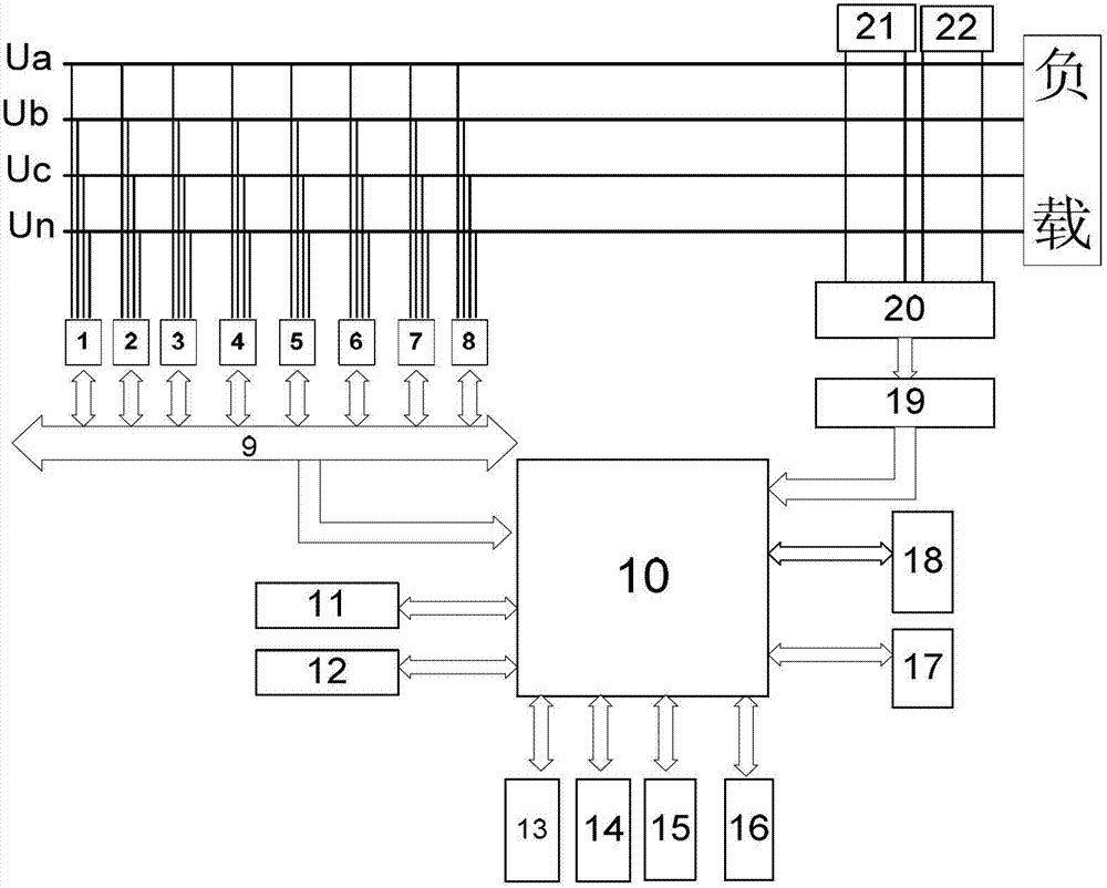
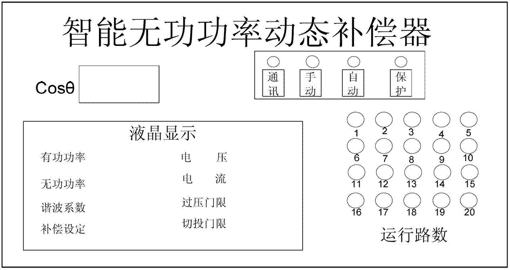
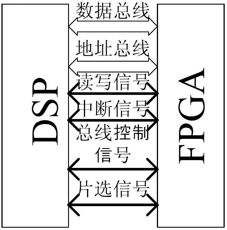
[0026] like figure 1 , figure 2 The structure of the present invention expressed is a reactive power compensation controller. In order to solve the problems existing in the prior art and overcome its defects, and realize the invention purpose of improving the working efficiency of reactive power compensation, the technical scheme adopted by the present invention is:

[0027] like figure 1 As shown, the reactive power compensation controller provided by the present invention is provided with multiple compensation modules, including static var compensator 1 ~ static var compensator 4 (SVC), static synchronous compensator 5 ~ Stat...


PUM


Abstract

The invention discloses a reactive compensation controller which is provided with a plurality of compensation modules. The reactive compensation controller comprises a static reactive compensator and a static synchronous compensator. The reactive compensation controller is further provided with a digital signal processor (DSP) control module. The static reactive compensator and the static synchronous compensator are connected with the DSP control module through a process filed bus (ProfiBus) module. In addition, a control method of the reactive compensation controller is further disclosed. According to the technical scheme, working efficiency of a compensation system is improved, loss is lowered, strong capacity, of dealing with mutation, of the system is ensured, dynamic response speed is higher, reliability is higher, service life is longer, system structure and construction are simple, products are conveniently manufactured in a modularized and standardized mode, dynamic reactive compensation technical level is favorable for being promoted, and construction of an intelligent power grid is promoted.

Description

technical field [0001] The invention belongs to the technical field of power quality management, and relates to its reactive power compensation technology. More specifically, the invention relates to a reactive power compensation controller. In addition, the invention also relates to a reactive power compensation method of the controller. Background technique [0002] With the development of science and technology, more and more users have adopted high-tech equipment with good performance and high efficiency, but are sensitive to changes in power characteristics, causing the power load to increase continuously; the increasing power load has caused a huge impact on the power grid , so that the power quality of the power grid deteriorates, which brings great pressure to the power quality control. In this context, there is an urgent need to increase the corresponding reactive power compensation device in the power grid to compensate the reactive power consumed by the load, imp...

Claims


Application Information

Patent Timeline
Patent Type & Authority Applications(China)
IPC IPC(8): H02J3/18H02J3/26
CPCY02E40/10Y02E40/50
Inventor 江明高文根连磊许钢袁一鸣汪石农江娟娟
Owner WUHU SHENJIAN YUCHANG NEW MATERIAL
Learn More