Thermal power plant circulating water system
A circulating water system and circulating water technology, applied in the directions of comprehensive factory control, comprehensive factory control, electrical program control, etc., can solve the problems of low temperature of circulating water at the inlet of the heat pump, difficulty in cleaning the condenser rubber ball, and affecting the performance of the heat pump, etc. Achieve the effect of economical improvement, safe and stable operation and simple structure
- Summary
- Abstract
- Description
- Claims
- Application Information
AI Technical Summary
Problems solved by technology
Method used
Image
Examples
Embodiment 1
[0046] Embodiment 1: thermal power plant circulating water system
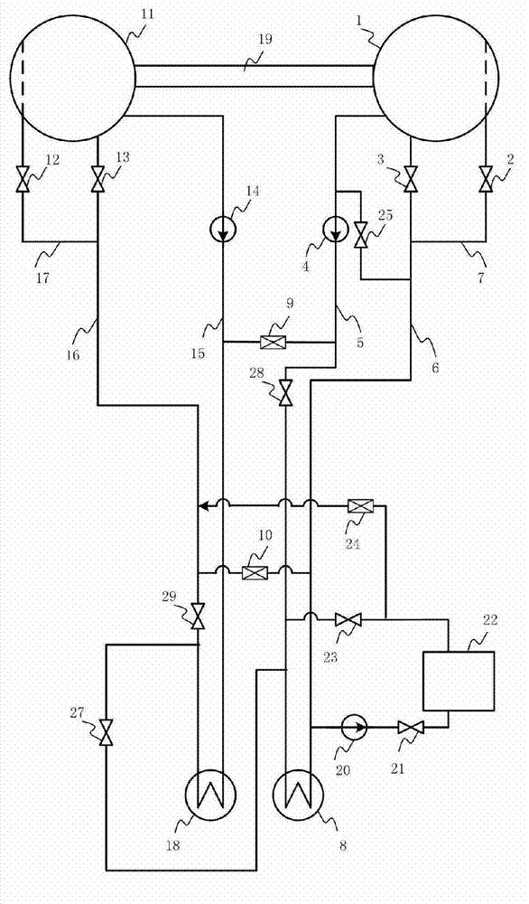
[0047] The circulating water system of the thermal power plant consists of the first unit and the second unit.
[0048] The circulating water system of the thermal power plant consists of the following:
[0049] The first unit consists of the first cooling tower 1, the first circulating water pump 4, the first condenser 8, the ice breaking pipeline valve 2, the circulating water return water main pipe valve 3, the circulating water pipeline valve 25 and the circulating water supply main pipe valve 28 Composition, the first cooling tower 1 is connected with the first condenser 8 through the first circulating water pump 4, the circulating water supply main pipe valve 28 and the circulating water supply main pipe 5, and the first condenser 8 is returned to the jellyfish through the circulating water The pipe 6 and the circulating water return jelly pipe valve 3 are connected to the first cooling tower 1, and the...
Embodiment 2
[0055] Embodiment 2: thermal power plant circulating water system
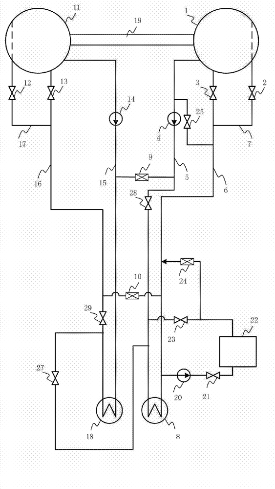
[0056] The circulating water system of the thermal power plant consists of the first unit and the second unit.
[0057] The circulating water system of the thermal power plant consists of the following:
[0058] The first unit consists of the first cooling tower 1, the first circulating water pump 4, the first condenser 8, the ice breaking pipeline valve 2, the circulating water return water main pipe valve 3, the circulating water pipeline valve 25 and the circulating water supply main pipe valve 28 Composition, the first cooling tower 1 is connected with the first condenser 8 through the first circulating water pump 4, the circulating water supply main pipe valve 28 and the circulating water supply main pipe 5, and the first condenser 8 is returned to the jellyfish through the circulating water The pipe 6 and the circulating water return jelly pipe valve 3 are connected to the first cooling tower 1, and the...
Embodiment 3
[0064] Embodiment 3: the use of the circulating water system of thermal power plant of the present invention
[0065] The implementation steps of this embodiment are as follows:
[0066] The thermal power plant circulating water system used in this embodiment is as attached figure 1 shown. The circulating water of the first unit comes out of the first cooling tower 1 and is boosted by the first circulating water pump 4, then enters the water side space of the first condenser 8 along the circulating water supply main pipe 5 to be heated, and then returns to the jellyfish along the circulating water The pipe 6 rises to the packing layer of the first cooling tower 1 through the valve 3 of the circulating water return jellyfish pipe, and its circulating water is cooled by the ambient air during the process of naturally falling into the storage tank, and then enters the first circulating water pump 4, and so on. ;
[0067] The circulating water of the second unit comes out of th...
PUM
 Abstract
Description
Claims
Application Information
 - R&D Engineer
- R&D Manager
- IP Professional
- Industry Leading Data Capabilities
- Powerful AI technology
- Patent DNA Extraction
Browse by: Latest US Patents, China's latest patents, Technical Efficacy Thesaurus, Application Domain, Technology Topic, Popular Technical Reports.
© 2024 PatSnap. All rights reserved.Legal|Privacy policy|Modern Slavery Act Transparency Statement|Sitemap|About US| Contact US: help@patsnap.com


