
Balancing and stabilizing mechanism of drawer slide rail

A sliding rail and balancing technology, applied in drawers, furniture parts, household appliances, etc., can solve the problems of asynchronous movement of the moving rails on both sides, inconsistent friction coefficients, high manufacturing process requirements, etc., to achieve convenient and fast installation, smooth pulling process, The effect of low manufacturing cost

Active Publication Date: 2013-04-10
伍志勇
View PDF5 Cites 16 Cited by
  • Summary
  • Abstract
  • Description
  • Claims
  • Application Information

AI Technical Summary

Problems solved by technology

The inner sliding rail, the outer fixed rail and the outer sliding rail are only connected by the rolling friction of the rollers, so that the inner sliding rail follows the outer sliding rail to move, but because the friction coefficients of the two moving rails are inconsistent, resulting in The movement is asynchronous; and the roller is set on the inner sliding rail by punching out the convex pin on the inner sliding rail. The manufacturing process of this convex pin is demanding and quite complicated, which is not convenient for the factory to manufacture.

Method used


Image

  • Balancing and stabilizing mechanism of drawer slide rail
  • Balancing and stabilizing mechanism of drawer slide rail
  • Balancing and stabilizing mechanism of drawer slide rail

Examples


Embodiment Construction

[0024] The present invention will be further described below in conjunction with the accompanying drawings and embodiments.

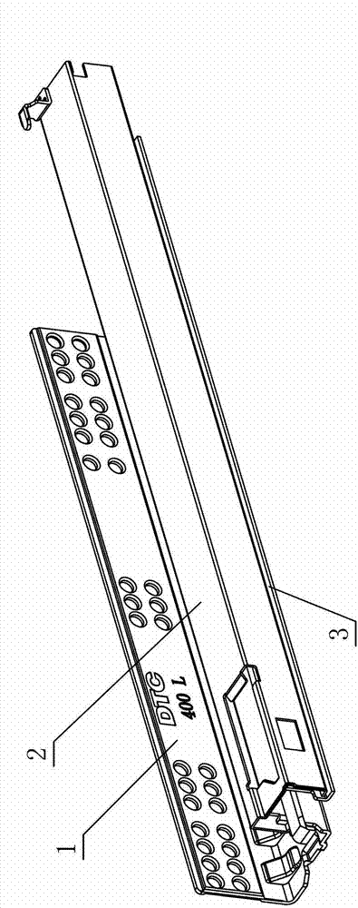
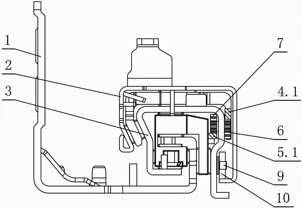
[0025] see Figure 1-Figure 9 , the balance and stability mechanism of the drawer slide rail includes a fixed slide rail 1 and a moving slide rail 2 that are slidingly connected, and a middle slide rail 3 is also arranged between the fixed slide rail 1 and the moving slide rail 2, and the three are slidingly connected to each other, wherein The middle slide rail 3 is slidably connected to the movable slide rail 2 through the first cage 4 , and the middle slide rail 3 is slidably connected to the fixed slide rail 1 through the second cage 5 . The middle slide rail 3 is provided with a double linkage gear set, and the two sets of gears of the double linkage gear set interact with the first rack 4.1 set on the first cage 4 and the second rack 5.1 set on the second cage 5 respectively. meshing, so that the fixed slide rail 1, the moving slide rail 2 and th...


PUM


Abstract

A balancing and stabilizing mechanism of a drawer slide rail comprises a fixed slide rail and a movable slide rail which are connected with each other in a sliding way, wherein a middle slide rail is arranged between the fixed slide rail and the movable slide rail; the fixed slide rail, the middle slide rail and the movable slide rail are connected with each other in a sliding way; the middle slide rail is connected with the movable slide rail through a first holding frame in a sliding way; the middle slide rail is connected with the fixed slide rail through a second holding frame in a sliding way; the balancing and stabilizing mechanism is characterized in that a duplex movable gear set is arranged on the middle slide rail; two groups of gears of the duplex movable gear set are respectively engaged with a first rack and a second rack, wherein the first rack is arranged on the first holding frame and the second rack is arranged on the second holding frame, so that the fixed slide rail, the movable slide rail and the middle slide rail slide relative to each other; and the duplex movable gear set is integrally arranged or integrally fixed and then embedded in the middle slide rail after being separately arranged. The balancing and stabilizing mechanism of the drawer slide rail, provided by the invention, has the advantages of convenience and rapidness in mounting and accurate positioning as the duplex movable gear set is integrally fixed after being separately arranged and finally embedded in the middle slide rail; moreover, as a roller arranged on the middle slide rail is connected with the movable slide rail through a pin separately arranged on the middle slide rail in a rolling way, the integral stamping of the pin on the middle slide rail is avoided, the manufacturing process for the middle slide rail is simplified and the production is more convenient.

Description

technical field [0001] The invention relates to a slide rail, in particular to a balance and stability mechanism for a drawer slide rail. Background technique [0002] Chinese Patent Document No. CN101530264 disclosed a drawer slide rail on September 16, 2009, which includes an outer fixed rail and an outer slide rail that are slidably connected to the inner slide rail through a cage, and rollers are positioned on the inner slide rail. The surfaces of the rollers are in close contact with the outer fixed rail and the outer sliding rail respectively, so as to realize the guided movement of the outer sliding rail and the inner sliding rail and improve the balance of each rail. The rollers are set on the side of the inner sliding rail through the positioning frame. The positioning frame is frame-shaped and fixed on the side of the inner sliding rail. The left and right sides of the inner wall are provided with shaft seats; In the frame, the two ends of the central shaft are re...

Claims


Application Information

Patent Timeline
IPC IPC(8): A47B88/10A47B88/493
Inventor 伍志勇
Owner 伍志勇
Learn More