A high-efficiency power generation floor tile
A floor tile, No. 1 technology, applied in the field of floor tiles and high-efficiency power generation floor tiles, can solve problems such as difficult manufacturing, complex structure, and single performance, and achieve the effects of low cost, improved power generation efficiency, and strong practicability
- Summary
- Abstract
- Description
- Claims
- Application Information
AI Technical Summary
Problems solved by technology
Method used
Image
Examples
Embodiment 1
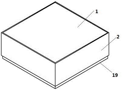
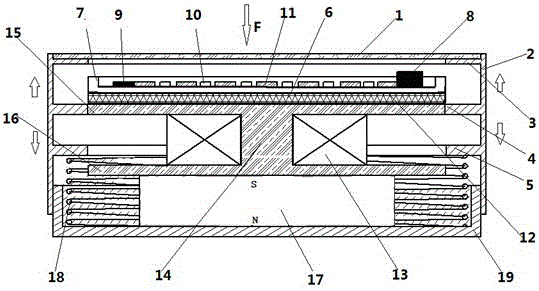
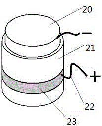
[0021] Embodiment 1: the structure of this embodiment is: as figure 1 and 2As shown, it includes a magnetically conductive top base 2 and a magnetically conductive base 19. A light-transmitting floor tile 1 is installed on the upper end of the magnetically conductive top base 2. There is a No. 1 magnetically conductive ring 4 in the middle of the interior. Magnetic ring 5; permanent magnet 17 is installed on the bottom of magnetic conduction base 19, magnet collector 14 is installed above permanent magnet 17, upper magnet collector 14 is upper magnet collector plate 15, the center is a column part, and the bottom is lower magnet collector plate 16 The middle cylinder part of the magnet collector 14 is wound with a magnetic induction coil 13, a lithium battery board 12 is arranged above the upper magnet collector board 15, an LED lamp board 6 is arranged above the lithium battery board 12, and a photosensitive switch 9 and a photosensitive switch 9 are arranged on the LED lamp ...
Embodiment 2
[0022] Embodiment 2: the structure of this embodiment is: as figure 1 and 2 As shown, it includes a magnetically conductive top base 2 and a magnetically conductive base 19. A light-transmitting floor tile 1 is installed on the upper end of the magnetically conductive top base 2. There is a No. 1 magnetically conductive ring 4 in the middle of the interior. Magnetic ring 5; permanent magnet 17 is installed on the bottom of magnetic conduction base 19, magnet collector 14 is installed above permanent magnet 17, upper magnet collector 14 is upper magnet collector plate 15, the center is a column part, and the bottom is lower magnet collector plate 16 The middle cylinder part of the magnet collector 14 is wound with a magnetic induction coil 13, a lithium battery board 12 is arranged above the upper magnet collector board 15, an LED lamp board 6 is arranged above the lithium battery board 12, and a photosensitive switch 9 and a photosensitive switch 9 are arranged on the LED lamp...
PUM
 Abstract
Description
Claims
Application Information
 - R&D
- Intellectual Property
- Life Sciences
- Materials
- Tech Scout
- Unparalleled Data Quality
- Higher Quality Content
- 60% Fewer Hallucinations
Browse by: Latest US Patents, China's latest patents, Technical Efficacy Thesaurus, Application Domain, Technology Topic, Popular Technical Reports.
© 2025 PatSnap. All rights reserved.Legal|Privacy policy|Modern Slavery Act Transparency Statement|Sitemap|About US| Contact US: help@patsnap.com


