Optical element, imaging lens unit, image pickup apparatus
A technology of optical components and lenses, applied in the field of image pickup devices, can solve problems such as difficult to remove
- Summary
- Abstract
- Description
- Claims
- Application Information
AI Technical Summary
Problems solved by technology
Method used
Image


Examples
no. 1 example
[0036] Configuration of Optical System in Image Pickup Device
[0037] figure 1 is an exemplary cross-sectional view showing the relationship between the optical system and incident light in the image pickup device according to the first embodiment of the present technology. The optical system of the first embodiment includes a first lens 110 having positive refractive power, a second lens 120 having negative refractive power, a third lens 130 having positive refractive power, and a fourth lens 140 having negative refractive power. Hereinafter, each of the first lens 110 to the fourth lens 140 is sometimes simply referred to as a 'lens'. Each lens has an effective diameter area corresponding to the effective diameter 70 which is centered on the optical axis 90 and which transmits the effective light beam. The part of the lens surrounding the effective diameter area is called the flange part. The side surface of the flange portion facing the object side is called an object s...
no. 3 example
[0061] Configuration of Optical System in Image Pickup Device
[0062] Figure 8 is an exemplary cross-sectional view showing a relationship between an optical system and incident light in an image pickup device according to a third embodiment of the present technology. Similar to the first embodiment, the optical system of the third embodiment includes a first lens 110 with positive refractive power, a second lens 120 with negative refractive power, a third lens 130 with positive refractive power, and a fourth lens 140 with negative refractive power . Similar to the first embodiment, the optical system further includes light shielding members 151 to 153 , a lens holder 160 , a filter 180 and an image pickup device 190 .
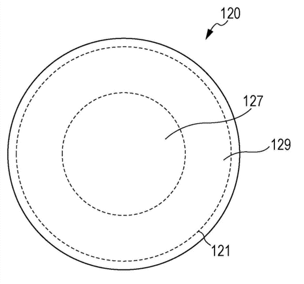
[0063] As described above, the concave portion 121 is provided in the outer edge portion of the image-side flange surface 129 of the second lens 120 in the first embodiment, while the concave portion 122 is provided in the inside of the image-side flange s...
no. 4 example
[0071] Configuration of Optical System in Image Pickup Device
[0072] Figure 10 is an exemplary cross-sectional view showing a relationship between an optical system and incident light in an image pickup device according to a fourth embodiment of the present technology. Similar to the first embodiment, the optical system of the fourth embodiment includes a first lens 110 with positive refractive power, a second lens 120 with negative refractive power, a third lens 130 with positive refractive power, and a fourth lens 140 with negative refractive power . Similar to the first embodiment, the optical system further includes light shielding members 151 to 153 , a lens holder 160 , a filter 180 and an image pickup device 190 .
[0073] Similar to the third embodiment described above, in the fourth embodiment, the recess 121 is provided in the outer edge portion of the image-side flange surface 129 of the second lens 120 , and the recess 122 is provided in the inner edge portion o...
PUM
 Abstract
Description
Claims
Application Information
 - R&D
- Intellectual Property
- Life Sciences
- Materials
- Tech Scout
- Unparalleled Data Quality
- Higher Quality Content
- 60% Fewer Hallucinations
Browse by: Latest US Patents, China's latest patents, Technical Efficacy Thesaurus, Application Domain, Technology Topic, Popular Technical Reports.
© 2025 PatSnap. All rights reserved.Legal|Privacy policy|Modern Slavery Act Transparency Statement|Sitemap|About US| Contact US: help@patsnap.com