
Sheath yarn winding device

A yarn tying device and sheath technology, applied in the direction of fiber mechanical structure, etc., can solve the problems of self-adjustment of tension, yarn accumulation and pitch, production troubles, etc., to achieve compact structure, stable equipment operation, The effect of low operating costs

Active Publication Date: 2013-04-03
NANJING WASIN FUJIKURA OPTICAL COMM LTD
View PDF4 Cites 5 Cited by
  • Summary
  • Abstract
  • Description
  • Claims
  • Application Information

AI Technical Summary

Problems solved by technology

However, in actual use, due to the large change in speed, sometimes there is an emergency brake, the self-adjustment of the tension cannot keep up, and the phenomenon of yarn breakage, yarn accumulation or skein and sudden change of pitch often occurs, causing great harm to production. troubled

Method used


Image

  • Sheath yarn winding device
  • Sheath yarn winding device
  • Sheath yarn winding device

Examples


Embodiment Construction

[0018] The solution of the present invention will be described in detail below in conjunction with the accompanying drawings.

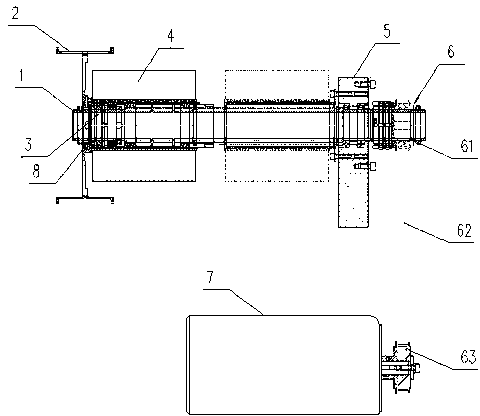
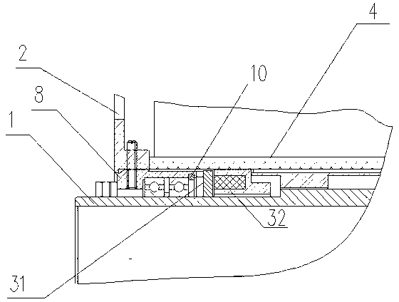
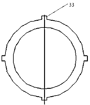
[0019] control Figure 1-2 , The sheath binding device provided by the present invention mainly consists of a rigid base 5, a hollow main shaft 1, an aircraft 2, a bearing 9, a bearing sleeve 8, a yarn ball cover 4 and a damper 3. The damper 3 includes a damping coil 32 and a friction plate 31; the hollow main shaft 1 is rotatably supported on the rigid base 5, and the bearing sleeve 8 is connected to the hollow main shaft 1 through a bearing. The inner ring of the bearing 9 is tightly fitted on the hollow main shaft 1 , and the outer ring of the bearing 9 is tightly fitted in the bearing sleeve 8 . One end of the bearing 9 abuts against the corresponding step surface of the bearing sleeve 8 , and the other end is limited by the circlip 10 to achieve axial positioning. The aircraft 2 is sleeved on one end of the bearing sleeve 8, and the two are con...


PUM


Abstract

The invention relates to a sheath yarn winding device which comprises a stiff stand, a hollow spindle, an aircraft, a bearing, a bearing sleeve, a yarn roll sleeve and a damper. The damper comprises a damping coil and a friction plate, the hollow spindle is rotatably supported on the stiff stand, the bearing sleeve is connected to the hollow spindle through the bearing, the aircraft without relative rotation is connected to the bearing sleeve, the damping coil is hollowly sleeved on the hollow spindle and does not rotate along with the hollow spindle, the friction plate is arranged between the damping coil and the bearing sleeve and connected with the bearing sleeve, and the yarn roll sleeve is hollowly sleeved on the outer sides of the bearing sleeve and the damper. The sheath yarn winding device has the advantages that yarn releasing tension is controlled by the hysteresis damper, various impact usually happening in operation of the device is avoided, abrasion is low, the device stably, safely and reliably runs and is simple to operate, pay-off tension is easily controlled, additionally, the structure is compact, and running cost in production is low.

Description

technical field [0001] The invention relates to optical cable production, in particular to a sheath binding device. Background technique [0002] The anti-seepage of the sheath process in the production of optical cables is a very important quality index. In order to prevent the intrusion of moisture in the optical cable in a humid environment and affect the transmission effect of the signal, it is necessary to wrap a layer of waterproof yarn on the outer layer of the optical cable. Waterproof yarn is used as a raw material for optical cable production and is wound on the corresponding outer diameter of the optical cable. When producing optical cable, a yarn binding device is required to wind the waterproof yarn around the outer diameter of the optical cable according to the process requirements. [0003] At present, the yarn binding device in the industry is equipped with a rotary sleeve on the top of the frame. One end of the rotary sleeve is connected to the driving devic...

Claims


Application Information

Patent Timeline
Patent Type & Authority Applications(China)
IPC IPC(8): G02B6/44
Inventor 王振云
Owner NANJING WASIN FUJIKURA OPTICAL COMM LTD
Learn More