
Optical fiber depolarizer with single-mode fiber serving as delay line

A single-mode fiber and depolarizer technology, which is applied to the coupling of optical waveguides and other directions, can solve the problems of high cost of fiber depolarizers and unstable performance of fiber depolarizers, and achieve the effect of reducing costs.

Active Publication Date: 2013-04-03
BEIJING AEROSPACE TIMES OPTICAL ELECTRONICS TECH
View PDF3 Cites 7 Cited by
  • Summary
  • Abstract
  • Description
  • Claims
  • Application Information

AI Technical Summary

Problems solved by technology

[0007] The technical problem to be solved by the present invention is: the Lyot fiber depolarizer is not suitable for the depolarization of the narrow line width light source, the performance of the existing single-mode fiber is unstable as the fiber depolarizer of the delay line, and the polarization maintaining Due to the high cost of fiber optic depolarizers used as delay lines, a stable fiber depolarizer using single-mode fibers as delay lines was proposed.

Method used


Image

  • Optical fiber depolarizer with single-mode fiber serving as delay line
  • Optical fiber depolarizer with single-mode fiber serving as delay line
  • Optical fiber depolarizer with single-mode fiber serving as delay line

Examples


Embodiment Construction

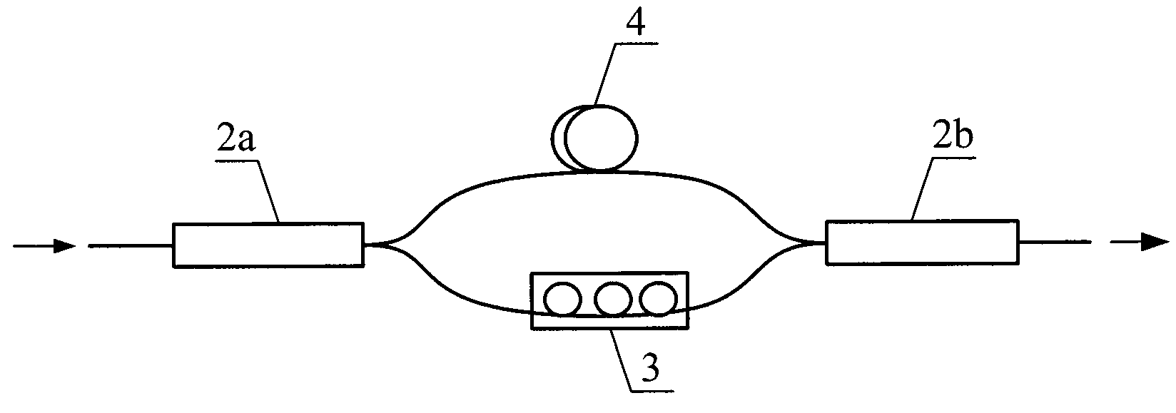
[0028] Such as image 3 As shown, a kind of fiber depolarizer utilizing single-mode fiber of the present invention as delay line is composed of single-mode fiber 4, fiber splitter 5, first polarization beam splitter 6a, second polarization beam splitter 6b, The Faraday rotating mirror 7 is formed; the beam combining port of the first polarization beam splitter 6a and the Faraday rotating mirror 7 are respectively connected to the two ends of the single-mode optical fiber 4 to form a delay optical path 8, and the two ends of the first polarization beam splitter 6a Two beam-splitting ports are respectively used as the input port and the output port of the delay optical circuit 8; two output ports of the optical fiber splitter 5 are respectively connected to the input port of the delay optical circuit 8 and a beam-splitting port of the second polarization beam splitter 6b, Another beam splitting port of the second polarization beam splitter 6b is connected to the output port of t...


PUM


Abstract

The invention discloses an optical fiber depolarizer with a single-mode fiber serving as a delay line. The optical fiber depolarizer comprises an optical fiber branching device, a first polarization beam splitter, the single-mode fiber, a faraday rotary reflector and a second polarization beam splitter. A beam combination port of the first polarization beam splitter and the faraday rotary reflector are connected to two ends of the single-mode fiber respectively to form a delay optical path, and two beam splitting ports of the first polarization beam splitter serve as an input port and an output port of the delay optical path respectively. The optical fiber branching device divides input light into two branches, one branch of light is directly inputted into one of beam splitting ports of the second polarization beam splitter, the other branch of light passes through the delay optical path to be inputted into the other beam splitting port of the second polarization beam splitter, and depolarized light is outputted from a beam combination port of the second polarization beam splitter. Cost of the optical fiber depolarizer is reduced by using the normal single-mode fiber as the delay line; and the polarization state is kept stable after the light passes through the delay optical path, and accordingly the optical fiber depolarizer can operate stably.

Description

Technical field [0001] The invention relates to an optical fiber depolarizer, in particular to an optical fiber depolarizer using a single-mode optical fiber as a delay line. Background technique [0002] In fiber optic interferometry, the contrast of the interference signal is affected by the polarization state of the light wave; when the polarization directions of the two interfering beams are consistent, the contrast of the interference signal is the largest; when the polarization directions of the two interfering beams are perpendicular, The contrast of the interference signal is zero. [0003] In order to ensure that the interference signal has a high contrast, a polarization-maintaining optical fiber and a polarization-maintaining optical device can be used to form a full polarization-maintaining optical path, so that the two beams of interference have the same polarization state, such as polarization-maintaining fiber optic gyroscopes and polarization-maintaining fibe...

Claims


Application Information

Patent Timeline
Patent Type & Authority Applications(China)
IPC IPC(8): G02B6/27
Inventor 唐才杰王巍王学锋崔留住姚锴
Owner BEIJING AEROSPACE TIMES OPTICAL ELECTRONICS TECH
Learn More