
Secondary optical lens for light emitting diode (LED) wide-angle bulb lamp and LED wide-angle bulb lamp

A secondary optical lens and LED light source technology, applied in the field of LED lighting, can solve the problems of difficult production, complex structure, poor heat dissipation effect, etc., achieve good heat dissipation effect and shorten the heat transfer path

Active Publication Date: 2014-06-25
HONGLI ZHIHUI GRP CO LTD
View PDF2 Cites 1 Cited by
  • Summary
  • Abstract
  • Description
  • Claims
  • Application Information

AI Technical Summary

Problems solved by technology

Most of the existing LED bulb lamps use plate-type LED integrated module light sources implanted in the bulb, and the light-emitting surface is narrow, which makes it impossible to realize all-round light.
The Chinese patent No. 200920206369.2 discloses "a bulb lamp". Although it can emit light at a large angle, it has a complicated structure and many contact surfaces. It is not only difficult to manufacture, but also has poor heat dissipation effect and short service life. Install high power LED
The Chinese invention patent application with the application number 201010146167.0 discloses "LED bulb lamp with improved luminous flux". The LED module is fixed on the slope. Azimuth lighting requirements, but also has the disadvantages of complex structure, difficult manufacture, poor heat dissipation effect, and short service life

Method used


Image

  • Secondary optical lens for light emitting diode (LED) wide-angle bulb lamp and LED wide-angle bulb lamp
  • Secondary optical lens for light emitting diode (LED) wide-angle bulb lamp and LED wide-angle bulb lamp
  • Secondary optical lens for light emitting diode (LED) wide-angle bulb lamp and LED wide-angle bulb lamp

Examples


Embodiment Construction

[0022] The present invention will be further described below in conjunction with the accompanying drawings of the description.

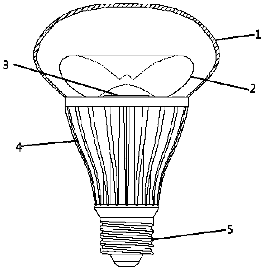
[0023] Such as figure 1 As shown, an LED wide-angle bulb lamp includes a lamp cap 5, a lamp holder arranged on the lamp holder 5, a radiator 4 arranged on the lamp holder, and a lamp body.

[0024] The radiator 4 is a hollow structure, with heat dissipation ribs around the outside, and a lamp body light-emitting driver for driving the bulb lamp inside the radiator. The driver is installed in the radiator, which can not only save space, but also make the bulb lamp smaller , and is conducive to the heat dissipation of the driver, the heat of the driver can be directly dissipated to the outside world through the radiator.

[0025] The lamp body includes a light-transmitting cover 1 and an LED light source assembly disposed inside the light-transmitting cover 1 . The transparent cover 1 is directly installed and fixed on the top of the radiator, and th...


PUM


Abstract

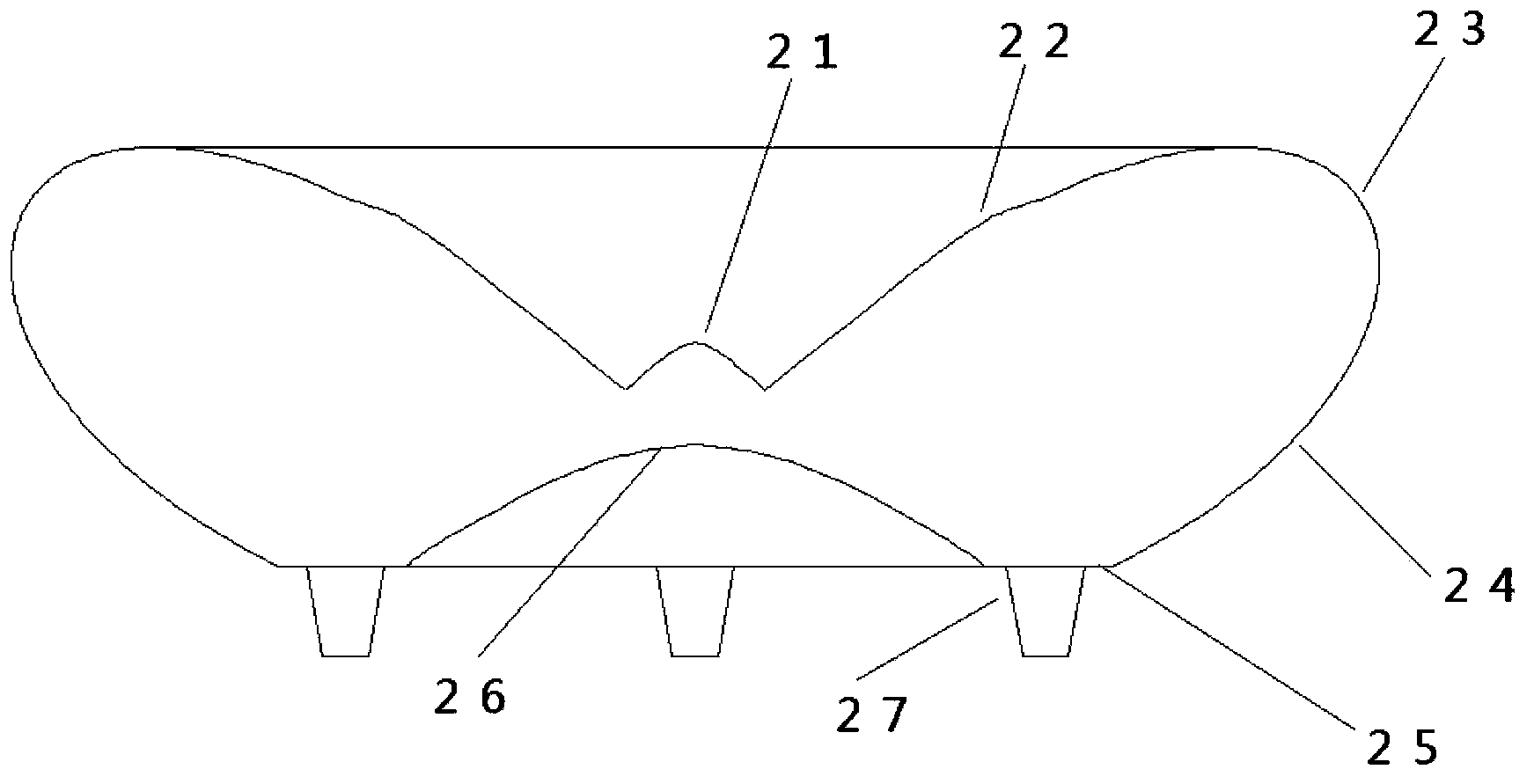
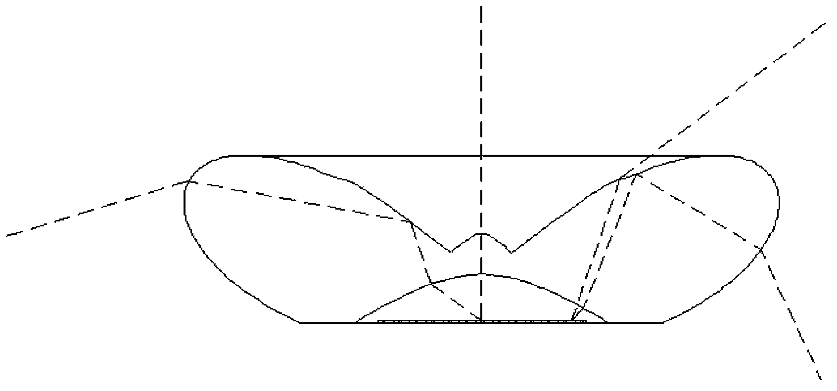
The invention discloses an LED wide-angle bulb lamp. The LED wide-angle bulb lamp comprises a secondary optical lens which is a revolving body, a ray incident plane at the bottom and four ray emergent planes at the top and around, wherein the first ray emergent plane refracts rays having relatively high energy in a light source central part to ensure enough illumination in an area between which and a central shaft the included angle is 0 to Alpha (Alpha is greater than or equal to 15 degrees and less than or equal to 45 degrees) under the bulb lamp; the second ray emergent plane refracts the light from the area of an area light source far away from the central part to supplement the illumination in the area between which and the central shaft the included angle is Alpha to Beta (Beta is greater than or equal to Alpha and less than or equal to 75 degrees) under the bulb lamp to ensure the illumination uniformity of the bulb lamp; and meanwhile, the light from the center of and the part around the area light source is totally reflected to be refracted on the third and fourth ray emergent planes to ensure enough illumination in the area between which and the central shaft the included angle is greater than Gamma (Gamma is greater than or equal to Beta and less than or equal to 180 degrees).

Description

technical field [0001] The invention relates to the field of LED lighting, in particular to an LED wide-angle bulb lamp for realizing wide-angle lighting. Background technique [0002] With the rapid development of LED technology, LED has gradually become the first choice for new green lighting due to its advantages of energy saving and environmental protection. Since incandescent lamps and electronic energy-saving lamps still occupy a very high proportion in daily use, in order to reduce waste, LED bulb lamps that use existing interfaces and do not need to replace the original traditional lamp bases and circuits came into being. For LED bulbs for indoor lighting, the basic requirements for their light intensity distribution and brightness are: the light bulb must not only have omnidirectional light, but also the light intensity distribution should be as uniform as possible to avoid uneven brightness and darkness, otherwise users will feel uncomfortable. repressed. In orde...

Claims


Application Information

Patent Timeline
Patent Type & Authority Patents(China)
IPC IPC(8): F21V5/04F21V17/10F21V29/00F21Y101/02F21V29/50F21V29/503F21Y105/00F21Y115/10
Inventor 余舒适熊威周镇王跃飞吴乾李国平
Owner HONGLI ZHIHUI GRP CO LTD
Learn More