
Backlight module

A backlight module and light source technology, applied in optics, light guides, light sources, etc., can solve the problem of increasing the distance required for light

Inactive Publication Date: 2013-04-03
TPV DISPLAY TECH (XIAMEN) CO LTD
View PDF4 Cites 14 Cited by
  • Summary
  • Abstract
  • Description
  • Claims
  • Application Information

AI Technical Summary

Problems solved by technology

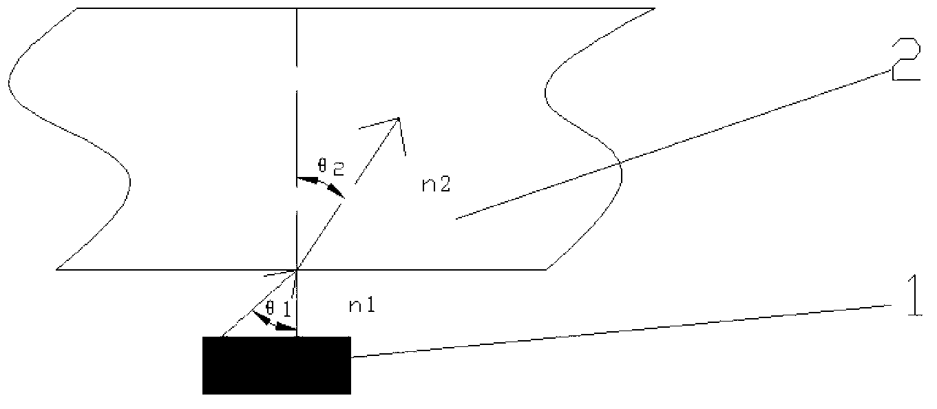
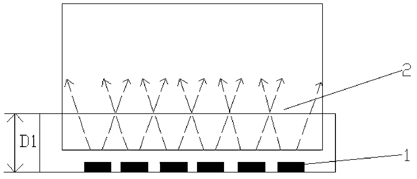
[0002] In the prior art, regardless of whether there is any other medium between the light emitting surface of the LED and the light incident surface of the light guide plate, the backlight module still has an air gap between the light emitting surface of the LED and the light incident surface of the light guide plate, and the light emitted by the LED must be Only through the air layer can it be incident into the light guide plate, such as figure 1 As shown, the refractive index n1 of air is 1, and the refractive index n2 of the light guide plate 2 is 1.49, which is substituted into the Snell’s formula On the light incident surface of the light guide plate, due to the difference in refractive index, Isnell's law shows that when light is incident from an optically sparse medium to an optically dense medium, the exit angle will be smaller than the incident angle. Therefore, even if the incident angle reaches 90 degrees, the exit angle is only 42 degrees, so the exit angle is smaller, so the distance required for the light to achieve uniform light mixing is increased, and it also causes a triangular dark area (hot spot) between the light sources

Method used


Image

  • Backlight module
  • Backlight module
  • Backlight module

Examples


Embodiment Construction

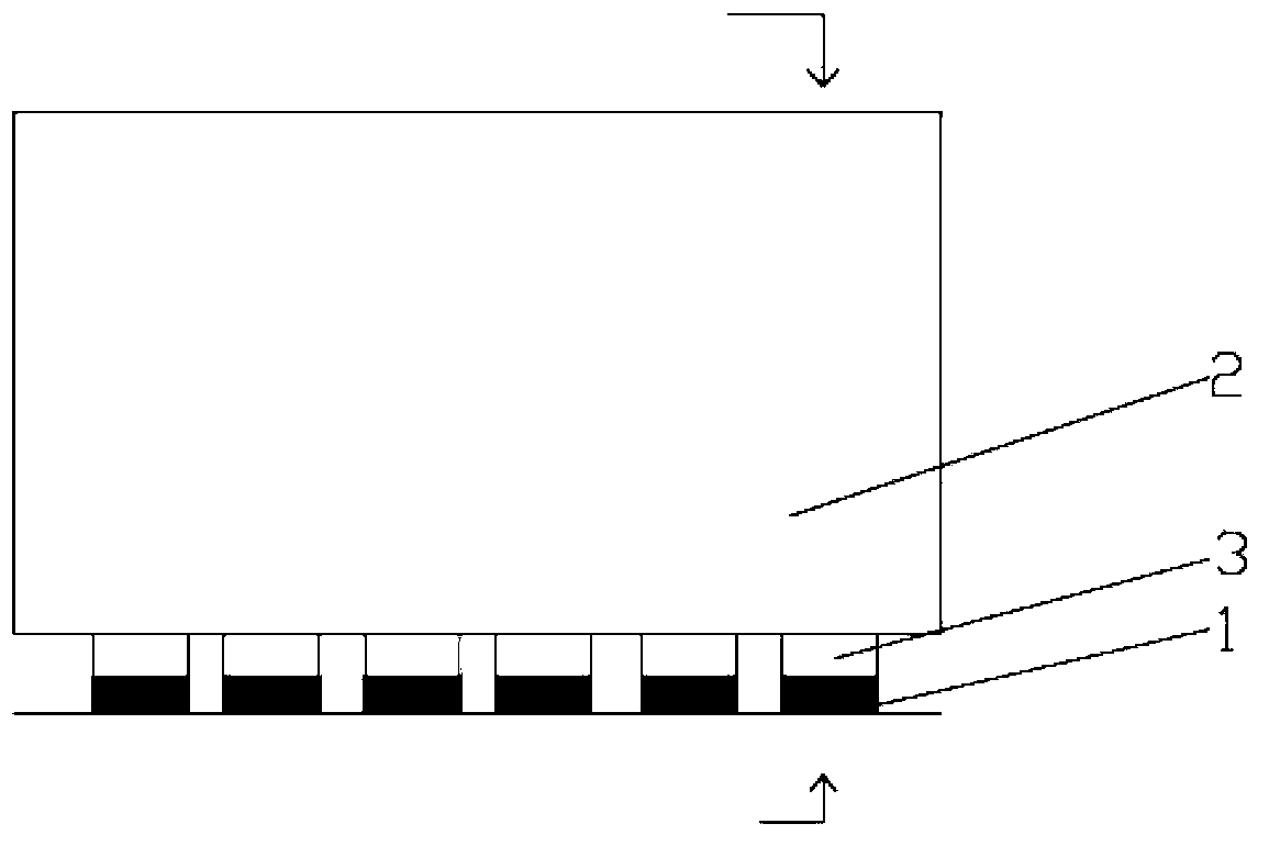
[0026] Such as image 3 , Figure 4 As shown, the backlight module of the present invention at least includes a light source 1, a light guide plate 2, and a light transmission structure 3. The light source 1 is composed of a plurality of LEDs, and the LED has a light emitting surface 11. The light guide plate 2 is made of transparent light guide Material molding, which includes a light incident surface 21 and a light exit surface 22 perpendicular to the light incident surface 21, the light transmission structure 3 is formed by a transparent light guide material, which includes a light incident surface 31 and a light incident surface 22 31 opposite to the light-emitting surface 32, which is arranged between the light-emitting surface 11 of the light source 1 and the light-receiving surface 21 of the light guide plate 2, and fills the gap between the light-emitting surface 11 of the light source 2 and the light-receiving surface 21 of the light guide plate 1, so The light emitt...


PUM

PropertyMeasurementUnit
The average particle sizeaaaaaaaaaa

Abstract

The invention discloses a backlight module which at least comprises a light source, a light guide plate and a light conduction structure. The light source consists of a plurality of LEDs (Light-Emitting Diodes); each LED is provided with a light extraction surface; the light guide plate is made of transparent light guide material and comprises a light entrance surface and a light extraction surface perpendicular to the light entrance surface; the light conduction structure is made of transparent light guide material, comprises a light entrance surface and a light extraction surface opposite to the light entrance surface, is arranged between the light extraction surface of the light source and the light entrance surface of the light guide plate and fills a gap between the light extraction surface of the light source and the light entrance surface of the light guide plate; the light extraction surface of the light source is connected with the light entrance surface of the light conduction structure; the light extraction surface of the light conduction structure is connected with the light entrance surface of the light guide plate; and light emitted by the light source is diffused by the light extraction surface of the light guide plate. According to the invention, the design of a narrower border is realized; and meanwhile, a light mixing distance at the light entrance side is not changed, an effect of uniformly mixing light is still achieved under the condition of reducing the number of the LEDs, and light entrance coupling efficiency between the light source and the light guide plate of the backlight module is strengthened.

Description

technical field [0001] The invention relates to a backlight module. Background technique [0002] In the prior art, regardless of whether there is any other medium between the light emitting surface of the LED and the light incident surface of the light guide plate, there is still an air gap between the light emitting surface of the LED and the light incident surface of the light guide plate in the backlight module, and the light emitted by the LED must be Only through the air layer can it be incident into the light guide plate, such as figure 1 As shown, the refractive index n1 of air is 1, and the refractive index n2 of the light guide plate 2 is 1.49, which is substituted into the Snell’s formula On the light-incident surface of the light guide plate, due to the difference in refractive index, Isnell's law shows that when the light is incident from an optically sparse medium to an optically dense medium, the exit angle will be smaller than the incident angle. Therefore,...

Claims


Application Information

Patent Timeline
IPC IPC(8): F21S8/00F21V8/00F21Y101/02
CPCG02B6/0023G02B6/0025
Inventor 郑俊义林博瑛林韡
Owner TPV DISPLAY TECH (XIAMEN) CO LTD
Learn More