
Automatic positioning paper-delivery shaft structure of journal printer

An automatic positioning and printer technology, applied in the direction of printing device, printing, etc., can solve the problem of inconvenient replacement of printing paper, and achieve the effect of simple structure and quick disassembly and assembly

Inactive Publication Date: 2013-04-03
NDT SCI & TECH
View PDF7 Cites 1 Cited by
  • Summary
  • Abstract
  • Description
  • Claims
  • Application Information

AI Technical Summary

Problems solved by technology

[0003] In order to overcome the technical deficiency of inconvenient replacement of printing paper in the paper delivery shaft structure used in the journal printer (sequence printer) in the prior art, the present invention discloses a journal printer automatic positioning paper delivery shaft structure, which can make The take-up shaft can be quickly disassembled into two parts, which is convenient for the replacement of printing paper rolls

Method used


Image

  • Automatic positioning paper-delivery shaft structure of journal printer
  • Automatic positioning paper-delivery shaft structure of journal printer
  • Automatic positioning paper-delivery shaft structure of journal printer

Examples


Embodiment Construction

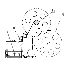
[0012] See attached figure 1 , when the log printer is working, the printing paper on the paper roll 9 is wound on the take-up shaft 12 through the intermediate roller, and the control module 11 controls the print head 10 to print the recorded information on the printing paper. When the printing paper is used up, , the printing paper needs to be taken off on the delivery shaft 12.

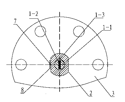
[0013] See attached figure 2 , 3 , 4, a journal printer disclosed in the present invention automatically locates the paper receiving shaft structure, comprising: a paper receiving shaft assembly, a left paper receiving baffle 3 installed on the paper receiving shaft assembly, a right paper receiving baffle 5 and a paper receiving shaft Gear 4, the delivery shaft assembly is composed of the left half shaft 2 and the right half shaft 1, one end of the left half shaft 2 is fixedly connected with the left baffle 3, and at the same time it is connected with the delivery shaft gear 4 Fixedly connecte...


PUM


Abstract

Disclosed is an automatic positioning paper-delivery shaft structure of a journal printer. The technical problem that the printing paper of a prior paper-delivery shaft structure is inconvenient to replace is solved. The technical scheme includes that the structure comprises a paper-delivery shaft assembly, a right paper-delivery baffle, a left paper-delivery baffle and a paper-delivery shaft gear, wherein the right paper-delivery baffle, the left paper-delivery baffle and the paper-delivery shaft gear are installed on the paper-delivery shaft assembly, the paper-delivery shaft assembly consists of a right paper-delivery half shaft and a left paper-delivery half shaft, one end of the left paper-delivery half shaft is fixedly connected to the left paper-delivery baffle and the paper-delivery shaft gear, the other end of the right paper-delivery half shaft is provided with a stair shat, a positioning bumping ball which is controlled by a spring is arranged on the stair shaft radially, one end of the right paper-delivery half shaft is fixedly connected to the right paper-delivery baffle, the other end of the left paper-delivery half shaft is provided with a shaft hole which is matched with the stair shaft, an annular axial positioning slot which is matched with the positioning bumping ball is arranged in the shaft hole, and an axial positioning pin which is used for preventing relative rotation is arranged on the combined end face of the right paper-delivery half shaft and the left paper-delivery half shaft. The device has the advantages of being simple in structure and quick and convenient for replacement of printing scroll s.

Description

technical field [0001] The invention relates to an automatic positioning take-up shaft structure used on a log printer (sequence printer), in particular to an automatic positioning take-up shaft structure suitable for a large paper roll journal printer with a diameter greater than 160 mm. Background technique [0002] With the development of information technology and high technology, self-service equipment is widely used in securities, banks, airports and other places, and plays an increasingly important role in our daily life. The log printer is one of the indispensable modules in most self-service equipment, which is used to record transaction information. Due to the widespread use of self-service equipment, the printing paper rolls used on printers need to be replaced frequently. The prior art uses a method of increasing the diameter of the paper rolls to reduce the number of times to replace the paper rolls. But still there is the technical deficiency that it is inconv...

Claims


Application Information

Patent Timeline
Patent Type & Authority Applications(China)
IPC IPC(8): B41J15/02
Inventor 郭礼虎黄伟雍继兵
Owner NDT SCI & TECH
Learn More