Eureka AIR delivers breakthrough ideas for toughest innovation challenges, trusted by R&D personnel around the world.

Intelligent floor wiping machine

A floor mopping machine, intelligent technology, applied in cleaning carpets, cleaning floors, machine parts, etc., can solve the problems of unsatisfactory cleaning effect, unsatisfactory sewage recycling effect, etc., to reduce weight and prolong the time of single work Effect

Inactive Publication Date: 2013-04-03
向桂南
View PDF11 Cites 80 Cited by
  • Summary
  • Abstract
  • Description
  • Claims
  • Application Information

AI Technical Summary

Problems solved by technology

The height of the water tank is lowered to achieve water circulation, but the same automatic feeding and washing system is set tangentially by the circular sponge roller and the extrusion roller, and the extrusion or scraping of the sponge roller by the extrusion roller is used for cleaning and washing. The effect is not ideal, and the recycling effect of sewage is not ideal

Method used


Image

  • Intelligent floor wiping machine
  • Intelligent floor wiping machine
  • Intelligent floor wiping machine

Examples


Embodiment 1

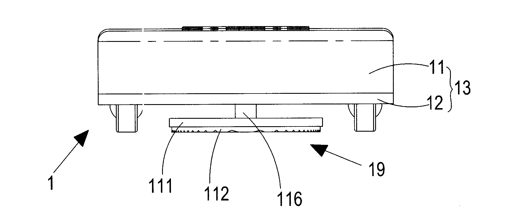
[0035] Such as Figure 4 , 5 As shown, the mopping machine main body 1 includes a housing 13 composed of an upper cover 11 and a lower bottom plate 12. A rechargeable battery 10 is installed inside the housing 13. The upper cover 11 is provided with a second connection for charging the rechargeable battery 10. Electrical terminal 121, the top of the upper cover 11 is provided with a receiving unit 124 for receiving signals transmitted by the transmitting unit 23. This receiving unit 124 can be a common omnidirectional or directional receiver, and the number can be set as one or more as required. The lower bottom plate 12 is provided with several moving wheel assemblies 14 that can drive the entire mopping machine main body 1 to move on the ground to be cleaned, and the moving wheel assembly 14 is equipped with a first drive unit that drives it to move. In this embodiment, the mobile wheel assembly 14 includes four wheel bodies in total, two of which are front wheels 15, and t...

Embodiment 2

[0038] Such as Figure 7 , 8 As shown, the mopping machine main body 1' includes a housing 13' composed of an upper cover 11' and a lower bottom plate 12'. A rechargeable battery 10' is installed inside the housing 13', and the upper cover 11' is provided with a battery for charging The second electrical connection terminal 121' for charging the battery 10', the top of the upper cover 11' is provided with a receiving unit 124' for receiving signals transmitted by the transmitting unit 23, this receiving unit 124' can be a common omnidirectional or directional receiver, The quantity can be set as one or more as required. The lower base plate 12' is provided with several moving wheel assemblies 14' that can drive the whole mopping machine main body 1' to move on the ground to be cleaned, and the moving wheel assembly 14' is equipped with a first drive unit that drives it to move. In this embodiment, the moving wheel assembly 14' includes a total of four wheel bodies, two of wh...


PUM


Abstract

The invention relates to an intelligent floor wiping machine, which comprises a floor wiping machine main body and a machine base which is connected with an external power supply. The floor wiping machine main body comprises a casing, a moving wheel assembly which is arranged on the bottom of the casing, a first driving unit which is used for driving the moving wheel assembly to move, a wet-type cleaning head assembly which is arranged on the bottom of the casing, and a receiving unit for receiving an external signal, and the machine base comprises a base body, a charging unit which is arranged on the base body, a cleaning unit which is arranged on the base body and is used for cleaning the cleaning head assembly, and an emitting unit for emitting a signal to the floor wiping machine main body. By the adoption of the floor wiping machine, by arranging the cleaning unit on the machine base, the weight of the floor wiping machine can be lightened during working, and thus the unit working time of the floor wiping machine is prolonged.

Description

technical field [0001] The invention relates to an intelligent mopping machine, which belongs to the field of daily cleaning, in particular to a water scrubbing and cleaning robot. Background technique [0002] Existing cleaning robots used for cleaning floors can free people from the tedious daily housework, and thus are welcomed by consumers. [0003] At present, there are many types of cleaning robots on the market, which are mainly used to clean the ground dust such as sweeping, vacuuming, washing, etc., and their functions are becoming more and more complete. Its main varieties are: intelligent electric sweepers, intelligent vacuum cleaners, and water scrubbing and cleaning robots. Among them, intelligent electric sweepers can only sweep large particles of garbage, but the cleaning effect on fine dust is not good, and it is easy to produce ash effect; due to the limitation of rechargeable battery power, intelligent vacuum cleaners are not capable of vacuuming. Strong,...

Claims


Application Information

Patent Timeline
Patent Type & Authority Applications(China)
IPC IPC(8): A47L11/293A47L11/40
Inventor 向桂南
Owner 向桂南
Why Eureka
Eureka Blog
Learn More