
Device and method for monitoring optical network performances

A monitoring device and optical network technology, applied in the field of optical communication, can solve the problems affecting data signal transmission performance, poor detection stability, etc., and achieve the effects of low detection bandwidth, simple implementation, and increased monitoring range

Inactive Publication Date: 2013-03-27
BEIJING UNIV OF POSTS & TELECOMM
View PDF3 Cites 13 Cited by
  • Summary
  • Abstract
  • Description
  • Claims
  • Application Information

AI Technical Summary

Problems solved by technology

[0009] The present invention provides an optical network performance monitoring device and monitoring method, which are used to solve the problem of simultaneously monitoring chromatic dispersion (CD, Chroma Dispersion) and polarization mode dispersion (PMD, Polarization) using RF spectrum (RF, Radio Frequency) technology in the prior art. Mode Dispersion), the transmitter needs to be modified, the added pilot component will affect the data signal transmission performance, and the detection stability is poor

Method used


Image

  • Device and method for monitoring optical network performances
  • Device and method for monitoring optical network performances
  • Device and method for monitoring optical network performances

Examples


Embodiment Construction

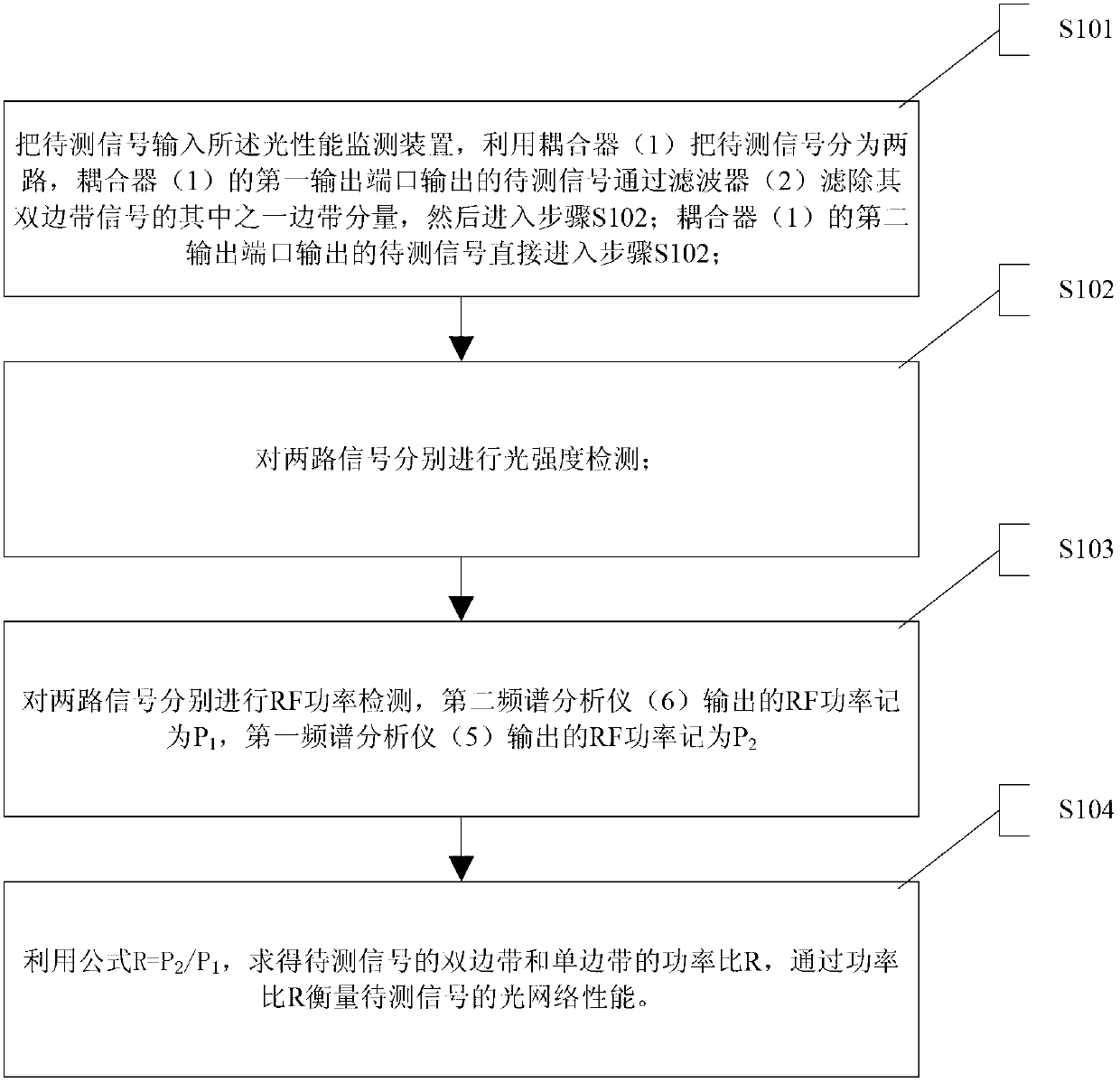
[0036] In order to better understand the present invention, the present invention will be further described below in conjunction with the accompanying drawings and specific embodiments.

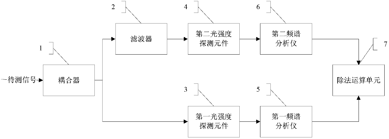
[0037] figure 1 is a schematic structural diagram of an optical network performance monitoring device according to an embodiment of the present invention, as shown in figure 1 As shown, an optical network performance monitoring device provided by an embodiment of the present invention includes: a coupler 1, a filter 2, a first light intensity detection element 3, a second light intensity detection element 4, a first spectrum analyzer 5, The second spectrum analyzer 6, division operation unit 7, wherein:

[0038] The coupler 1 is used to divide the signal to be tested into two paths, input the signal to be tested to the input port of the coupler 1, the first output port of the coupler 1 is connected to the input port of the filter 2, The second output port of the coupler 1 is connected to th...


PUM


Abstract

A device for monitoring optical network performances comprises a coupler (1), a filter (2), a first light intensity detection element (3), a second light intensity detection element (4), a first spectrum analyzer (5), a second spectrum analyzer (6) and a division operation unit (7). According to the device and a method for monitoring optical network performances, in a high-speed dynamic reconfigurable optical add and drop multiplexer, a radio frequency (RF) spectrum technology is used for achieving a chromatic dispersion (CD) monitoring technology of insensitive polarization mode dispersion (PMD), and CD and PMD can be monitored independently and simultaneously. The method is simple to implement, the device structure is simple, the detection bandwidth is low, a transmitter is not needed to be modified, the monitoring sensitivity is improved apparently, and the monitoring range is increased.

Description

technical field [0001] The invention relates to the technical field of optical communication, in particular to an optical network performance monitoring device and a monitoring method. Background technique [0002] In optical communication networks, in order to ensure good service quality, the importance of optical network performance monitoring becomes more and more prominent. Radio frequency spectrum analysis technology is a commonly used performance monitoring technology. Damage caused by spontaneous emission noise (ASE, Amplified Spontaneous Emission), fiber dispersion, etc. will change the intensity and phase of the signal. After intensity detection, it will show certain characteristics in the signal radio frequency spectrum. Radio frequency spectrum analysis technology, that is, the monitoring technology that extracts these features by filtering and other methods to monitor the damaged optical signal-to-noise ratio, is the key technology. This technology has the chara...

Claims


Application Information

Patent Timeline
Patent Type & Authority Applications(China)
IPC IPC(8): H04B10/07
Inventor 伍剑李兰兰陈亮
Owner BEIJING UNIV OF POSTS & TELECOMM
Learn More