Method for controlling reactive voltage in ultra-high voltage grid on the basis of improved economic voltage difference

An ultra-high voltage, power grid technology, applied in reactive power compensation, reactive power adjustment/elimination/compensation, etc., can solve the problem that the loss of the UHV power grid cannot be minimized, and the reactive power layer balance and reactive power compensation cannot be fully paid attention to. The switching strategy is complex and other problems, to reduce the frequency of switching operations, ensure real-time balance, and achieve the effect of real-time balance

Active Publication Date: 2013-03-27
CHINA ELECTRIC POWER RES INST +2
View PDF2 Cites 16 Cited by
  • Summary
  • Abstract
  • Description
  • Claims
  • Application Information

AI Technical Summary

Problems solved by technology

However, under this method, the voltage control and reactive power control are basically decoupling control, and the main goal is to control the bus voltage within a reasonable range. It fails to fully pay attention to the requirements of reactive power layered balance, and the UHV power grid loss cannot be minimized.
[0005] In the initial stage of UHV power grid construction, the grid structure is relatively simple, and this control strategy is simple and easy to implement, and has good adaptability; with the continuous strengthening of UHV power grid, the number of incoming and outgoing lines of hub substations continues to increase, and the power flow of lines changes frequently, " Designing UHV substation reactive power compensation switching strategies based on changes in transmission power of UHV lines will become increasingly complex and difficult to implement

Method used


Image

  • Method for controlling reactive voltage in ultra-high voltage grid on the basis of improved economic voltage difference
  • Method for controlling reactive voltage in ultra-high voltage grid on the basis of improved economic voltage difference
  • Method for controlling reactive voltage in ultra-high voltage grid on the basis of improved economic voltage difference

Examples


Embodiment Construction

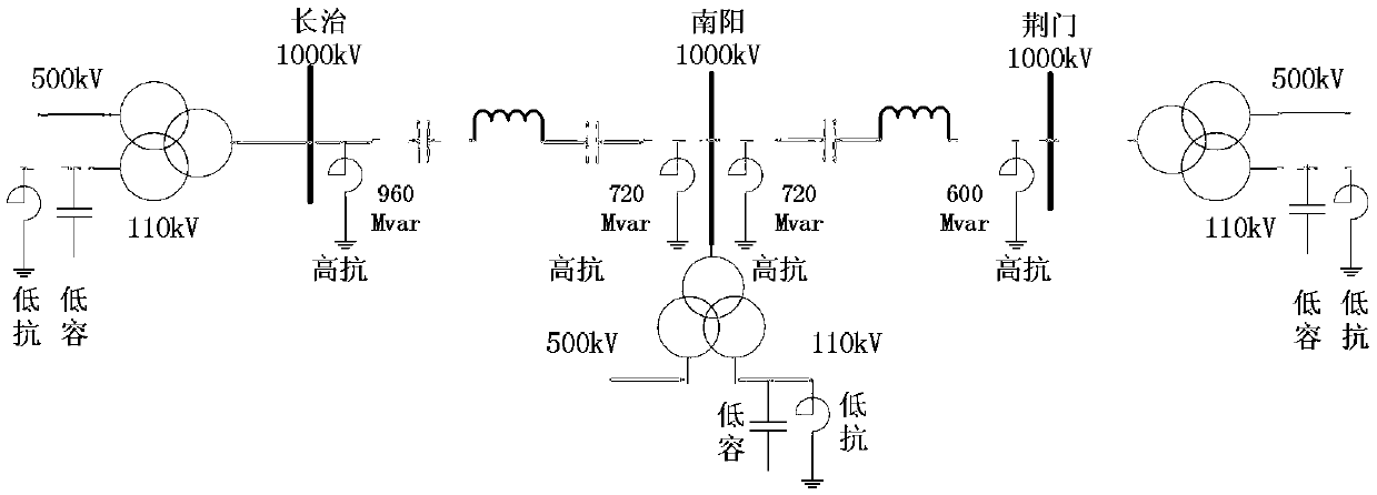
[0028] Taking the UHV Changzhi-Nanyang line as an example, the Nanyang-Jingmen line will not be considered for the time being. Consider installing 20% ​​series compensation on both sides of the Changnan Line, and consider 2*3000MVA for transformers on both sides.

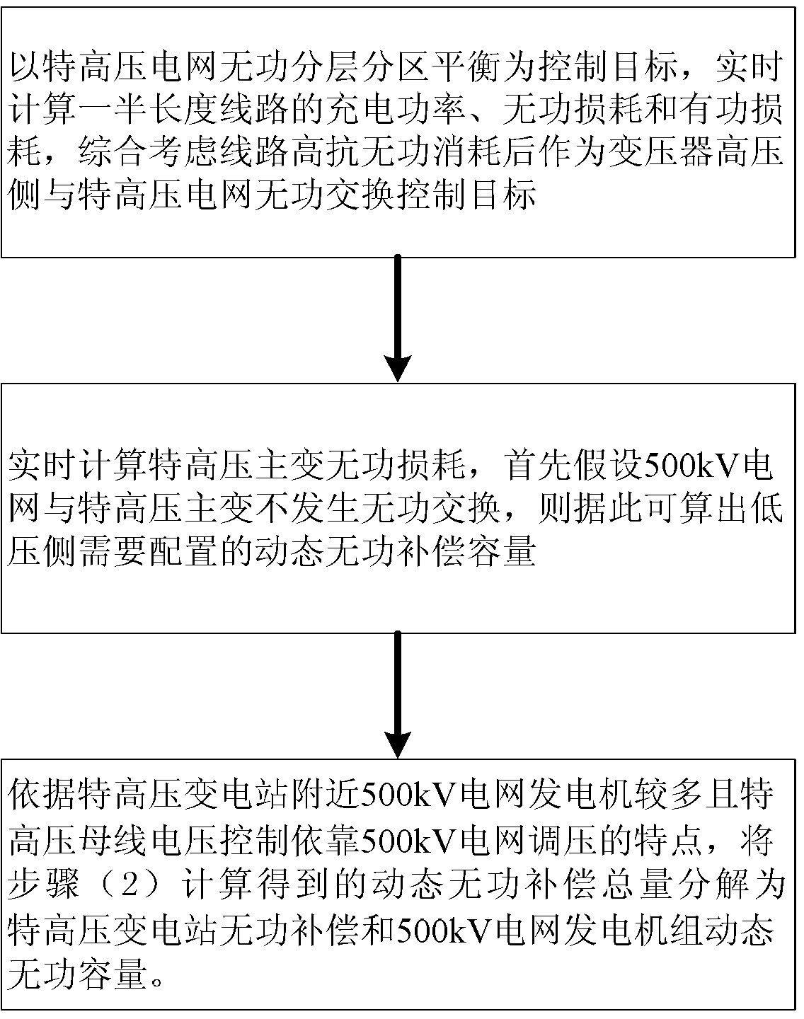
[0029] The specific steps of the reactive voltage control method of the UHV grid based on the improved economic pressure difference of the present invention are as follows:

[0030] (1) Taking the reactive power stratified and zoned balance of the UHV power grid as the control objective, calculate the charging power, reactive power loss and active power loss of half the length of the line in real time, and comprehensively consider the reactive power consumption of the line as the high voltage side of the transformer and the UHV power grid Reactive power exchange control target, the calculation results are shown in Table 1.

[0031] (2) Real-time calculation of the reactive power loss of the UHV main transformer, the react...


PUM


Abstract

The invention provides a method for controlling reactive voltage in an ultra-high voltage grid on the basis of improved economic voltage difference. For current simulation and problems in controlling the reactive voltage in the ultra-high voltage grid, the reactive voltage in the ultra-high voltage grid is balanced in real time by real-time coordination of low voltage side conventional reactive compensation with 500kV grid dynamic reactive compensation. The method allows real-time coordinated control for the low voltage side reactive compensation and 500kV grid side dynamic reactive compensation, and ensures real-time reactive power and efficient and economic operation of the ultra-high voltage grid. In addition, by the use of the method, operating frequency in conventional compensation switching can be reduced greatly, reactive loss of transformers is lowered further, and busbar voltage fluctuation caused by power fluctuation of tie lines is suppressed to a certain degree.

Description

Technical field [0001] The invention belongs to the field of electric power systems, and in particular relates to a reactive voltage control method of an UHV power grid based on an improved economic pressure difference. Background technique [0002] On the basis of ensuring the safe and stable operation of the power grid, in order to improve the economic benefits of power grid operation and reduce active power loss and investment, various reactive power optimization algorithms and voltage and reactive power automatic control devices have been greatly developed and played a good role. The reactive power optimization problem is a multi-variable, multi-constrained hybrid nonlinear programming problem. Its control variables include continuous variables such as generator terminal voltage, and discrete variables such as capacitor / reactor switching, transformer tap adjustment, etc. The convergence reliability and calculation speed of its numerical solution are the key to its practical a...

Claims


Application Information

Patent Timeline
IPC IPC(8): H02J3/18
CPCY02E40/30
Inventor 唐晓骏王刚魏胜民李晶姚淑玲罗红梅黄景慧李晓珺田华王一振
Owner CHINA ELECTRIC POWER RES INST
Why Eureka
Try Eureka