Cold source temperature control method and device of flue gas waste heat recovery device

A temperature control method and flue gas waste heat technology, which are applied in heat exchange equipment, lighting and heating equipment, and greenhouse gas reduction, etc., can solve problems such as failure to reach set values, wall temperature fluctuations, and system oscillations, and achieve improved control. quality, preventing undershoot or overshoot, improving the effect of large inertia and large hysteresis

Inactive Publication Date: 2013-03-27
广东中节能环保有限公司
View PDF9 Cites 14 Cited by
  • Summary
  • Abstract
  • Description
  • Claims
  • Application Information

AI Technical Summary

Problems solved by technology

The specific performance is: in the traditional control system, when the control command is issued, a cold source temperature adjustment cycle has not yet ended or the controlled object has not responded in time, and the system operating environment may change again. At this time, the control system collects After the new parameter is changed, a new control instruction will be issued, which will cause the system to oscillate and cause the wall temperature to fluctuate to a certain extent. It cannot reach the set value for a period of time, that is, it cannot maintain its wall temperature at the acid temperature. Above the dew point, it is difficult to obtain the expected control effect

Method used


Image

  • Cold source temperature control method and device of flue gas waste heat recovery device
  • Cold source temperature control method and device of flue gas waste heat recovery device
  • Cold source temperature control method and device of flue gas waste heat recovery device

Examples


Embodiment Construction

[0054] In order to facilitate the understanding of the present invention, an embodiment is given in conjunction with the accompanying drawings to further illustrate the present invention.

[0055] Step 1: Parameter collection. The temperature sensor installed in the heat exchanger will measure the temperature of cold water in the heat exchanger, hot water temperature, cold source water temperature in the mixing water tank, heat exchange wall temperature of the heat exchanger, and flue gas temperature. Five parameters are collected;

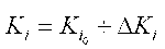
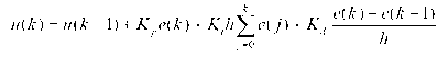
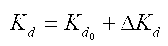
[0056] Step 2: The data unit calculates the temperature error e and the temperature difference change ec based on the parameters collected in step 1, and sends the temperature error e and the temperature difference change ec to the fuzzy controller. The relationship between the temperature difference e and the temperature difference change ec The formula is:

[0057]

[0058] The symbols in the formula have the same meaning as the text.

[...


PUM


Abstract

The invention relates to a cold source temperature control method of a flue gas waste heat recovery device. The method mainly comprises the steps of parameter collection, data processing, fuzzy reasoning, controlled quantity outputting, controlling execution and the like. The method specifically comprises the steps of: calculating a temperature error e and a temperature difference change ec with a reference set temperature by collecting parameters such as cold water temperature, hot water temperature, temperature of a mixed water tank, heat exchange wall temperature and exit gas temperature in the flue gas waste heat recovery device; and then, obtaining control parameters by fuzzy reasoning, and adjusting the cold source temperature by controlling a cold source water electric adjusting executor and a flowback water electric adjusting executor through the parameters. According to the invention, with the adoption of an advanced fuzzy predicting method, deviation, size change and direction as well as time relationship of the controlled volume are effectively pre-compensated according to a fuzzy rule established by real time identification of the system, so that short of adjustment or over-adjustment is prevented, the influence to the performance of the control system due to great inertia and large hysteresis in the controlled process is improved, and the control quality is improved.

Description

technical field [0001] The invention relates to the field of waste heat recovery, and relates to a cold source temperature control method and device for flue gas waste heat recovery equipment that can automatically track and clamp the lowest wall temperature of a single-stage or multi-stage cold end to be above the acid dew point and within a fixed value range. Background technique [0002] The exhaust gas temperature of the factory design and operation of the boiler accounts for a large proportion of the heat loss of the boiler. Making full use of the waste heat of the exhaust gas not only meets the requirements of energy conservation and emission reduction policies, but also reduces the energy cost of the enterprise at the same time. [0003] At present, flue gas waste heat utilization equipment is gradually being commercialized. Waste heat technology in flue gas can be divided into direct heat exchange and indirect heat exchange. [0004] (1) The direct heat ...

Claims


Application Information

Patent Timeline
Patent Type & Authority Applications(China)
IPC IPC(8): F23J15/06F28F27/00
CPCY02E20/30
Inventor 孙淮林赵强吕宁朱和锦黄从智郑丽平
Owner 广东中节能环保有限公司
Why Eureka
Try Eureka