Special shaped block and retaining wall

A block and special-shaped technology, applied in the field of block-stacked walls, can solve problems such as excessive material consumption, complicated construction, and long construction period, and achieve the effects of simple stacking, material saving, and cost reduction

Inactive Publication Date: 2013-03-27
王崧骅
View PDF5 Cites 0 Cited by
  • Summary
  • Abstract
  • Description
  • Claims
  • Application Information

AI Technical Summary

Problems solved by technology

[0002] Most of the blocks used in the existing construction industry are solid or hollow bricks, which can only be bonded with mortar materials to form a single-layer wall, that is, a retaining wall is constructed by using a wet-laying process. There is a lot of material and a long construction period, which cannot meet the market demand. Therefore, it is necessary to develop a block that can form a retaining wall by dry laying

Method used


Image

  • Special shaped block and retaining wall
  • Special shaped block and retaining wall
  • Special shaped block and retaining wall

Examples


Embodiment 2

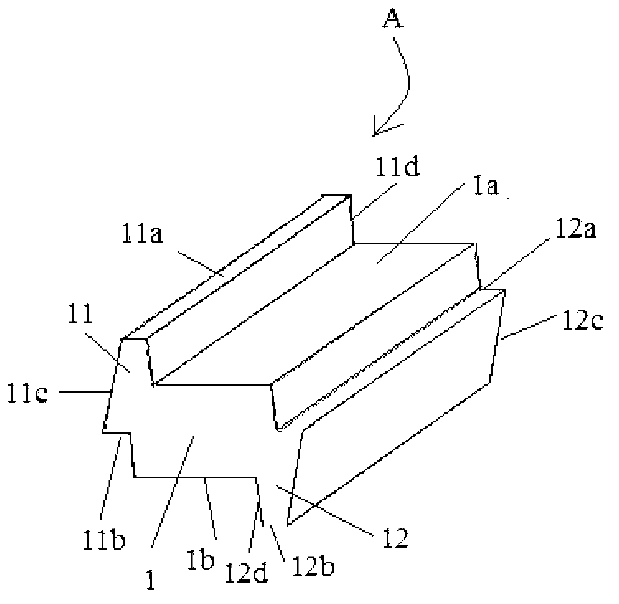
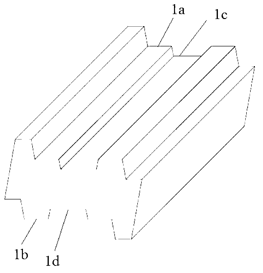
[0028] see figure 2 , the difference between this embodiment and Embodiment 1 is:

[0029] 1. In the special-shaped block in this embodiment, a central groove 1c is provided on the upper surface 1a of the main body, and a central groove 1d is provided on the lower surface 1b of the main body. Setting the central groove can reduce the weight of special-shaped blocks;

[0030] 2. In this embodiment, the bottom of the first protrusion is lower than the transverse central plane of the main body, and correspondingly, the top of the second protrusion is higher than the transverse central plane of the main body.

[0031] For the special-shaped blocks given in the above examples, in the actual implementation process, according to actual needs, different first protrusions and second protrusions can be selected. For example, the bottom of the first protrusion is lower For special-shaped blocks on the transverse central plane of the main body and the top of the second protrusion is hi...

Embodiment 1

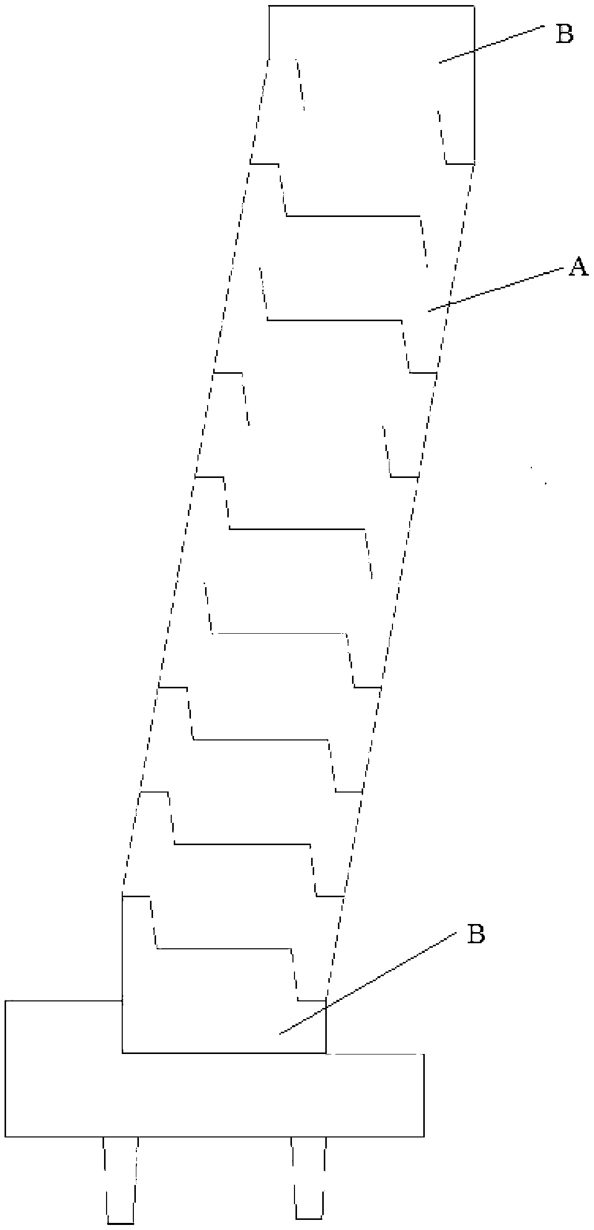
[0033] see image 3 , the retaining wall in this embodiment is composed of several special-shaped blocks to form the main body of the wall, and an end block B is respectively arranged at the top and bottom of the main body of the wall; wherein, the structure of the special-shaped block A in this embodiment The structure is the same as that of the special-shaped block in the first embodiment of the above-mentioned special-shaped block, and will not be repeated here.

[0034] The retaining wall formed by stacking the above special-shaped blocks will form a number of ecological holes when it is sparsely laid. The resulting retaining wall has the functions of self-retaining and self-draining. The retaining wall is weakened and collapsed, and sand-free concrete positioning blocks are placed behind each ecological hole as a filter.

[0035] Example 2 of the retaining wall

[0036] see Figure 4 , the retaining wall in this embodiment is composed of several special-shaped blocks A...

Embodiment 3

[0038] see Figure 5 , the retaining wall in this embodiment is composed of several special-shaped blocks A to form the main body of the wall, and an end block B is respectively arranged at the top and bottom of the main body of the wall; wherein, the first block of the special-shaped block in this embodiment The outer parts of the first protrusion and the second protrusion are slopes at an angle of 45 degrees to the horizontal plane.


PUM


Abstract

The invention discloses a special shaped block which comprises a long-stripe main body, a first protruding portion and a second protruding portion, wherein the first protruding portion is located at the position of the end portion of the upper side of the main body, the second protruding portion is located at the position of the end portion of the lower side of the main body, the first protruding portion is a ladder-shaped protrusion which upwards protrudes on an upper surface of the main body, the second protruding portion is a ladder-shaped protrusion which downwards protrudes on a lower surface of the main body, the first protruding portion and the second protruding portion are symmetrical relative to a transverse central face of the main body, and the protruding portion and the second protruding portion are located on different sides of the main body. A first groove is arranged on the main body below the bottom of the first protruding portion, area of the top portion of the first groove and area of the top portion of the first protruding portion are same, and gradient of the lateral portion of the first groove and gradient of an inner lateral portion of the first protruding portion are same. A second groove is arranged on the main body above the top portion of the second protruding portion, area of the bottom of the second groove and the area of the top portion of the second protrusion are same, and gradient of the lateral portion of the second groove and gradient of the inner lateral portion of the second protruding portion are same. The invention further discloses a retaining wall.

Description

technical field [0001] The invention relates to the technical field of walls built with blocks, in particular to a special-shaped block and a retaining wall. Background technique [0002] Most of the blocks used in the existing construction industry are solid or hollow bricks, which can only be bonded with mortar materials to form a single-layer wall, that is, a retaining wall is constructed by using a wet-laying process. There is a lot of material and a long construction period, which cannot meet the market demand. Therefore, it is necessary to develop a block that can form a retaining wall by dry laying. Contents of the invention [0003] In view of this, the purpose of the present invention is to provide a special-shaped block, through reasonable and ingenious structural arrangement, so that the various-shaped blocks can be combined with each other to form a retaining wall without subsequent reinforcement. Based on this, the present invention also provides a retaining ...

Claims


Application Information

Patent Timeline
IPC IPC(8): E02D29/02
Inventor 王崧骅
Owner 王崧骅
Why Eureka
Try Eureka