Automobile emergency brake alarm system and control method thereof

An emergency braking and alarm system technology, applied in vehicle components, optical signals, signal devices, etc., can solve the problems of rear-end collision, insufficient braking, and easy deviation, and achieve the effect of preventing rear-end collision accidents, simple structure and good practicability.

Inactive Publication Date: 2013-03-27
CHERY AUTOMOBILE CO LTD
View PDF5 Cites 11 Cited by
  • Summary
  • Abstract
  • Description
  • Claims
  • Application Information

AI Technical Summary

Problems solved by technology

[0002] The brake system is the key active safety system of the car, but the current brake system cannot distinguish between normal brakes and emergency brakes. As long as the brake pedal is stepped on, the brake lights at the rear of the car will light up, and the vehicles behind cannot judge based on the brake lights. Whether the vehicle in front is braking in an emergency can only be judged by visually measuring the distance between vehicles, and deviations are prone to occur
For example, when a vehicle is driving at high speed on a highway or on a general road, emergency braking is required when there is an unexpected situation ahead or an emergency turn is required. If the vehicle behind uses the brake as a normal brake, there may be insufficient braking , leading to tailgating

Method used


Image

  • Automobile emergency brake alarm system and control method thereof

Examples


Embodiment 1

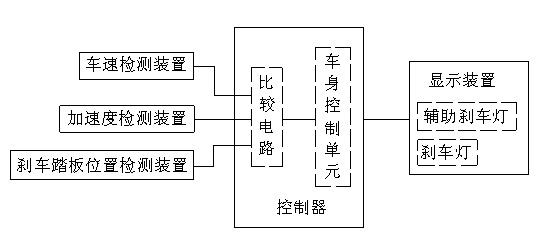
[0013] Such as figure 1 As shown, the automobile emergency braking alarm system of this embodiment includes a display device, an acceleration detection device, a brake pedal position detection device, a vehicle speed detection device and a controller, wherein the controller is composed of a comparison circuit and a vehicle body control unit, and the controllers are respectively It is connected with a display device, an acceleration detection device, a brake pedal position detection device, and a vehicle speed detection device.

[0014] The control method of the above-mentioned automobile emergency braking alarm system is as follows: the comparison circuit in the controller receives the signals of the acceleration detection device, the brake pedal position detection device and the vehicle speed detection device at the same time. When the vehicle speed is predetermined, the comparison circuit sends a signal to the vehicle body control unit, and the vehicle body control unit cont...


PUM


Abstract

The invention aims at providing an automobile emergency brake alarm system and a control method thereof. The automobile emergency brake alarm system can timely and clearly notify vehicles, behind a vehicle performing brake, of the brake situation of the vehicle through a brake display lamp, thereby preventing the occurrence of rear-end collision accidents. The automobile emergency brake alarm system provided by the invention comprises a display device, an acceleration detection device, a brake pedal position detection device and a controller, wherein the controller is used for receiving signals of the acceleration detection device and the brake pedal position detection device, and controlling the display of the display device according to the signals. The control method of the automobile emergency brake alarm system is as follows: receiving the signals of the acceleration detection device and the brake pedal position detection device through the controller, and controlling the display device to display that the vehicle is in an emergency brake state by the controller when a brake pedal is trampled down and acceleration exceeds the preset acceleration.

Description

technical field [0001] The invention relates to an automobile emergency braking alarm system applicable to various vehicle braking systems and a control method thereof. Background technique [0002] The brake system is the key active safety system of the car, but the current brake system cannot distinguish between normal brakes and emergency brakes. As long as the brake pedal is stepped on, the brake lights at the rear of the car will light up, and the vehicles behind cannot judge based on the brake lights. Whether the vehicle in front is braking in an emergency can only be judged by visually measuring the distance between vehicles, and deviations are prone to occur. For example, when a vehicle is driving at high speed on a highway or on a general road, emergency braking is required when there is an unexpected situation ahead or an emergency turn is required. If the vehicle behind uses the brake as a normal brake, there may be insufficient braking , leading to tailgating. ...

Claims


Application Information

Patent Timeline
Patent Type & Authority Applications(China)
IPC IPC(8): B60Q1/44
Inventor 邓维仆沈玉欣
Owner CHERY AUTOMOBILE CO LTD
Why Eureka
Try Eureka