Mechanical 3D (Three Dimensional) probe
A 3D, mechanical technology, applied in the field of ultrasonic imaging, can solve the problems of hindering the propagation of ultrasonic waves, affecting the diagnosis and judgment of doctors, and the entry of external gas into confined spaces, so as to reduce the risk of leakage
- Summary
- Abstract
- Description
- Claims
- Application Information
AI Technical Summary
Problems solved by technology
Method used
Image
Examples
Embodiment 1
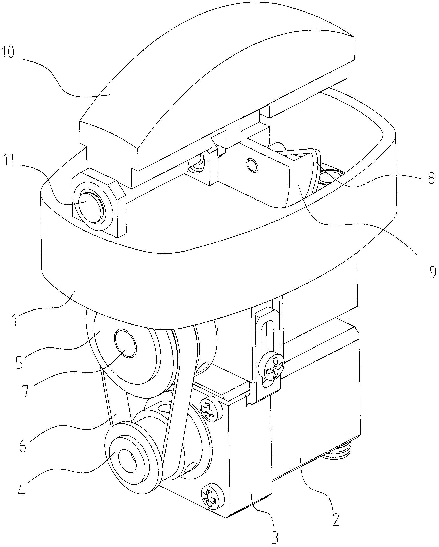
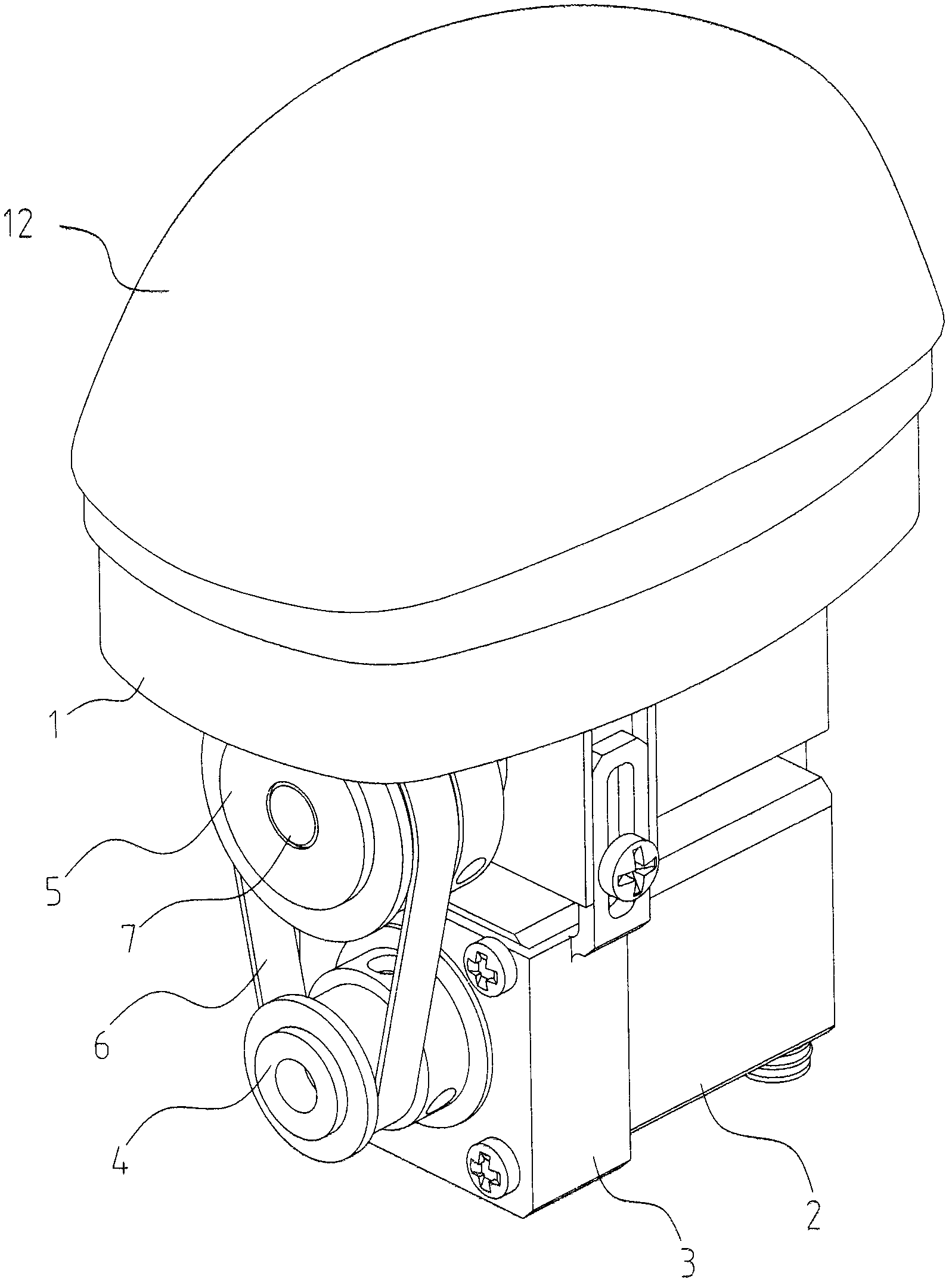
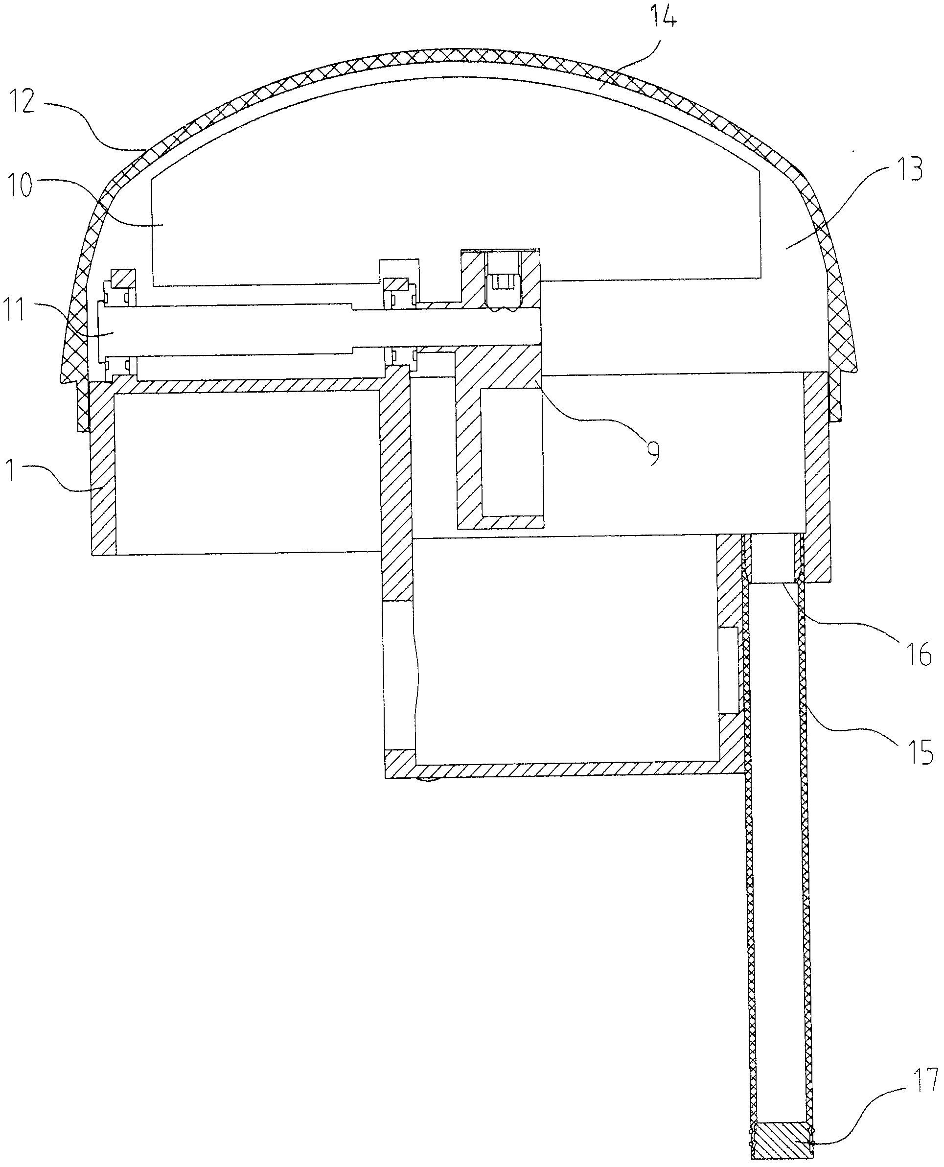
[0033] like Figure 4 , 5 As shown, a mechanical 3D probe includes a base 1, an acoustic window 12, and a flexible pipe 15. The acoustic window 12 is connected to the base 1, and the acoustic window 12 and the base 1 form a A closed space 13 for loading coupling liquid, the sound head 10 is arranged in the closed space 13, a through hole 1a is provided on the base 1 to communicate with the closed space 13; the head end of the hose 15 is an opening end, the end is a closed end, the first end of the hose 15 is connected to the through hole 1a of the base 1, the end of the hose 15 extends into the closed space 13, and the outer wall of the end of the hose 15 is directly coupled with the The inner cavity of the hose 15 communicates with the air outside the closed space 13 .
[0034] The cross-section of the hose 15 is a common concentric circle, the inner chamber of the hose is opened at both ends of the hose, and the head end of the hose 15 is tightly pressed in the through hol...
Embodiment 2
[0043] like Figure 6 , 7 As shown, the cross section of the hose 15 is a common concentric circle, the inner cavity of the hose 15 is opened at the head end of the hose 15 , and the inner cavity of the hose 15 is closed at the end of the hose 15 . The open end of hose 15 is tightly pressed in the through hole 1a of base 1 through a plug 16 with a hole, and the end of hose 15 stretches into closed space 13, and the outer wall of the end of hose 15 is connected with the coupling liquid in closed space 13. direct contact.
[0044] The difference of the second embodiment with respect to the first embodiment is that the inner chamber of the flexible pipe 15 is opened at the head end of the flexible pipe 15, and is closed at the end of the flexible pipe 15, so it is not necessary to perform sealing treatment at the end of the inner cavity of the flexible pipe 15 , so the structure is simpler.
Embodiment 3
[0046] like Figure 8 , 9 As shown, the cross section of the hose 15 is non-circular, and the inner chamber of the hose 15 is open at the head end of the hose 15 and closed at the end of the hose 15 . The open end of hose 15 is tightly pressed in the through hole 1a of base 1 through a plug 16 with a hole, and the end of hose 15 stretches into closed space 13, and the outer wall of the end of hose 15 is connected with the coupling liquid in closed space 13. direct contact.
[0047] The third embodiment is different from the second embodiment in that: the cross section of the hose 15 is non-circular, the cross section of the hose 15 can be flexibly designed according to the actual situation, and the area surrounded by the inner contour of the hose 15 is also relatively large. Under the condition of the same length, the inner volume of the hose 15 is larger, which can compensate for the larger volume change of the coupling fluid in the closed space.
PUM
 Abstract
Description
Claims
Application Information
 - R&D
- Intellectual Property
- Life Sciences
- Materials
- Tech Scout
- Unparalleled Data Quality
- Higher Quality Content
- 60% Fewer Hallucinations
Browse by: Latest US Patents, China's latest patents, Technical Efficacy Thesaurus, Application Domain, Technology Topic, Popular Technical Reports.
© 2025 PatSnap. All rights reserved.Legal|Privacy policy|Modern Slavery Act Transparency Statement|Sitemap|About US| Contact US: help@patsnap.com


