
Cooker and display device

A cooker and display technology, which is applied in the field of display devices, can solve problems such as difficult switching of images, and achieve the effects of reducing time and burden, fast switching, easy switching and selection

Active Publication Date: 2013-03-20
SHARP KK
View PDF4 Cites 3 Cited by
  • Summary
  • Abstract
  • Description
  • Claims
  • Application Information

AI Technical Summary

Problems solved by technology

[0004] However, in the above-mentioned conventional display device, since it is necessary to operate a plurality of keys, there is a problem that it is difficult to switch images.

Method used


Image

  • Cooker and display device
  • Cooker and display device
  • Cooker and display device

Examples


Embodiment Construction

[0108] Next, the heating cooker and the display device of the present invention will be described in detail using the illustrated embodiments.

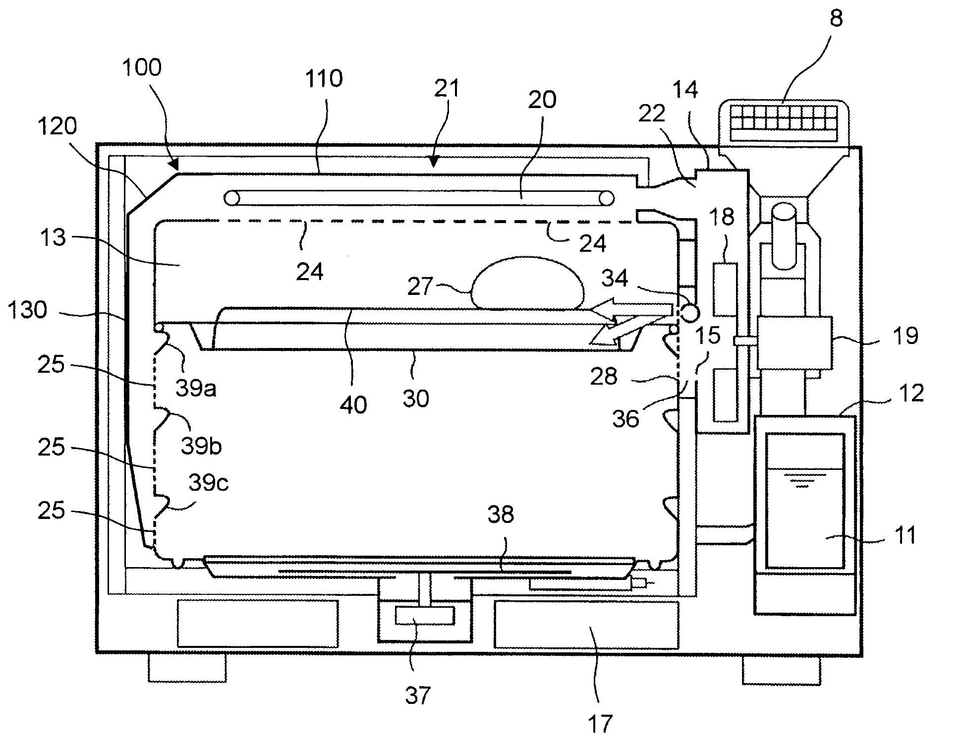
[0109] figure 1 It is a front perspective view of the heating cooker which concerns on one Embodiment of this invention.

[0110] The above-mentioned heating cooker is provided with a door 2 mounted on the front of a rectangular parallelepiped box 1, and the door 2 is rotated substantially centering on the side at the lower end side. A handle 3 is attached to the upper portion of the door 2 , and a heat-resistant glass 4 is attached to the approximate center of the door 2 . Furthermore, an operation panel 5 is provided on the right side of the door 2 . The operation panel 5 has a color liquid crystal display unit 6 and a button group 7 . In addition, an exhaust duct 8 is provided on the upper side of the box body 1 and on the rear right side. In addition, a dew-receiving container 9 is detachably attached below the door 2 of the b...


PUM


Abstract

Provided is a cooker which is provided with: a cooking recipe storage unit (202) which stores a plurality of cooking recipes; a color liquid crystal panel (61), which displays some of the cooking recipes stored in the cooking recipe storage unit (202); a touch panel (62); a control unit (200), which sequentially switches the cooking recipes displayed on the color liquid crystal panel (61) when a sliding / moving operation is performed by keeping a finger or a contact material touching the surface of the touch panel (62); and a cooking unit (203), which performs cooking on the basis of the cooking recipe selected by the touch panel (62).

Description

technical field [0001] The present invention relates to a heating cooker, and to a display device for, for example, a heating cooker or the like. Background technique [0002] Conventionally, there is a display device attached to a heating cooker described in Japanese Patent Laid-Open Publication No. 2002-349858 (Patent Document 1). The above-mentioned display device includes: a display part provided on the front of the heating cooker cabinet; and a plurality of keys for switching images displayed on the display part. [0003] According to the conventional display device described above, the user can switch the image on the display unit to another image by operating a plurality of keys, thereby displaying a desired image on the display unit. [0004] However, in the conventional display device described above, since it is necessary to operate a plurality of keys, there is a problem that it is difficult to switch images. [0005] Patent Document 1: Japanese Patent Laid-Open...

Claims


Application Information

Patent Timeline
Patent Type & Authority Applications(China)
IPC IPC(8): F24C7/02F24C15/00G06F3/0488G09F9/00G09G5/00
CPCF24C7/082H05B6/6435
Inventor 能澤利佳胜浦高明田中稔冨松広和延藤智子
Owner SHARP KK
Learn More