
Electromagnetic compatibility passive control type adjustable load circuit and box applying circuit

A passive control type, electromagnetic compatibility technology, applied in the field of electromagnetic compatibility, can solve problems such as abnormal operation, low efficiency, and many connecting wires, and achieve the effect of convenient debugging, remarkable effect, and fixed position

Active Publication Date: 2013-03-20
广电计量检测集团股份有限公司
View PDF3 Cites 2 Cited by
  • Summary
  • Abstract
  • Description
  • Claims
  • Application Information

AI Technical Summary

Problems solved by technology

[0005] But it has the following defects and deficiencies: there are many connecting wire ends, many components, inconvenient to build, and unreliable contact; the long section of the wire harness is not consistent with the placement position, and the position of the wire harness placement has an impact on the measurement results; adjustable sliding Resistors have low precision, cumbersome debugging, and low efficiency; poor test data reproducibility, inaccurate test results, etc.
[0007] However, it has the following defects and deficiencies: Although the active electronic load can simply debug the load carried by the product under test, there is a control circuit inside the active load, which needs to be connected to the power grid or powered by other methods to work
In the disturbance test, because of the electromagnetic disturbance of the active load itself, it seriously interferes with the test results of the product under test; Radiated immunity test and conducted immunity test
No matter in the electromagnetic disturbance project test or the electromagnetic immunity project test, there is a risk that the test result is inaccurate and may even be misjudged that the product under test is unqualified due to the electromagnetic compatibility problem caused by the load itself

Method used


Image

  • Electromagnetic compatibility passive control type adjustable load circuit and box applying circuit
  • Electromagnetic compatibility passive control type adjustable load circuit and box applying circuit
  • Electromagnetic compatibility passive control type adjustable load circuit and box applying circuit

Examples


Embodiment Construction

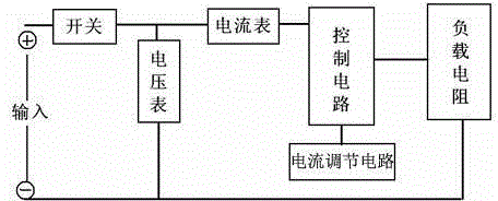
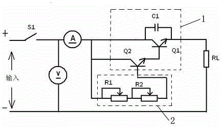
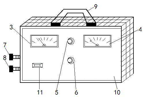
[0021] like figure 1 , 2 As shown, the electromagnetic compatibility passive control type adjustable load circuit, which includes the main circuit switch S1, DC ammeter A, DC voltmeter V, current regulation circuit 1 connected with DC ammeter A, and control circuit connected with DC ammeter A 2. The load resistance RL, the main circuit switch S1 is connected to the positive pole of the power product under test, and the main circuit switch S1 is respectively connected to the DC ammeter A and the DC voltmeter V; the current regulation circuit 1 is connected to the control circuit 2; one end of the load resistance RL is connected to the control circuit 2 and the current regulating circuit 1, and the other end is connected to the negative pole of the power supply product under test.

[0022] Its internal circuit structure is simple, and there are no logic circuits, switching circuits, pulse generating circuits and other circuits that are prone to electromagnetic disturbance insid...


PUM


Abstract

The invention relates to the technical field of electromagnetic compatibility and specifically relates to an electromagnetic compatibility passive control type adjustable load circuit and a box applying the circuit. The electromagnetic compatibility passive control type adjustable load circuit comprises a circuit master switch S1, a direct current ammeter A, a direct current voltmeter V, a current adjusting circuit, a control circuit and a load resistor RL, the current adjusting circuit and the control circuit are connected with the direct current ammeter A, and the circuit master switch S1 is connected with a positive pole of a tested power supply product, the direct current ammeter A and the direct current voltmeter V; the current adjusting circuit is connected with the control circuit; and one end of the load resistor RL is connected with the control circuit and the current adjusting circuit, and the other end of the load resistor RL is connected with a negative pole of the tested power supply product. According to the electromagnetic compatibility passive control type adjustable load circuit and the box applying the circuit, the circuit can work without additional power supplies, no electromagnetic radiation can be generated, the cost is low, the performance is reliable, the using is convenient and rapid, and the effect is obvious.

Description

technical field [0001] The invention relates to the technical field of electromagnetic compatibility, in particular to an electromagnetic compatibility passive control adjustable load circuit and a box applying the circuit. Background technique [0002] In the electromagnetic compatibility test for low-power general-purpose power products, it is often necessary to artificially add a load equivalent to the power marked on the power product, and compare and test it under three operating modes of full load, half-load and no-load to find out the maximum The working mode of the electromagnetic disturbance radiation value is tested. [0003] There are currently two commonly used testing methods, [0004] Method 1 Slide a resistive load. It consists of 1. Ammeter; 2. Voltmeter; 3. Adjustable sliding resistor; 4. Each connecting wire forms a load network, which is connected to the voltage output port of the power product under test to provide a load to make it work normally. [0...

Claims


Application Information

Patent Timeline
IPC IPC(8): G01R31/40
Inventor 张雄吴煜民
Owner 广电计量检测集团股份有限公司
Learn More