
Detection device of bonding strength between rotor core and magnet ring

A technology of bonding strength and rotor iron core, applied in the direction of measuring devices, mechanical devices, instruments, etc., can solve problems such as the inability to accurately reflect the bonding strength of the rotor iron core and the magnetic ring, achieve convenient operation, accurate detection accuracy, and ensure The effect of pass rate

Active Publication Date: 2013-03-20
SUZHOU LING AUTOMATION EQUIP
View PDF5 Cites 9 Cited by
  • Summary
  • Abstract
  • Description
  • Claims
  • Application Information

AI Technical Summary

Problems solved by technology

At present, there is no suitable detection instrument to detect the bonding strength between the rotor core and the magnetic ring. Generally, a multifunctional detector is used instead, so it cannot accurately reflect the actual bonding strength between the rotor core and the magnetic ring.

Method used


Image

  • Detection device of bonding strength between rotor core and magnet ring
  • Detection device of bonding strength between rotor core and magnet ring
  • Detection device of bonding strength between rotor core and magnet ring

Examples


Embodiment

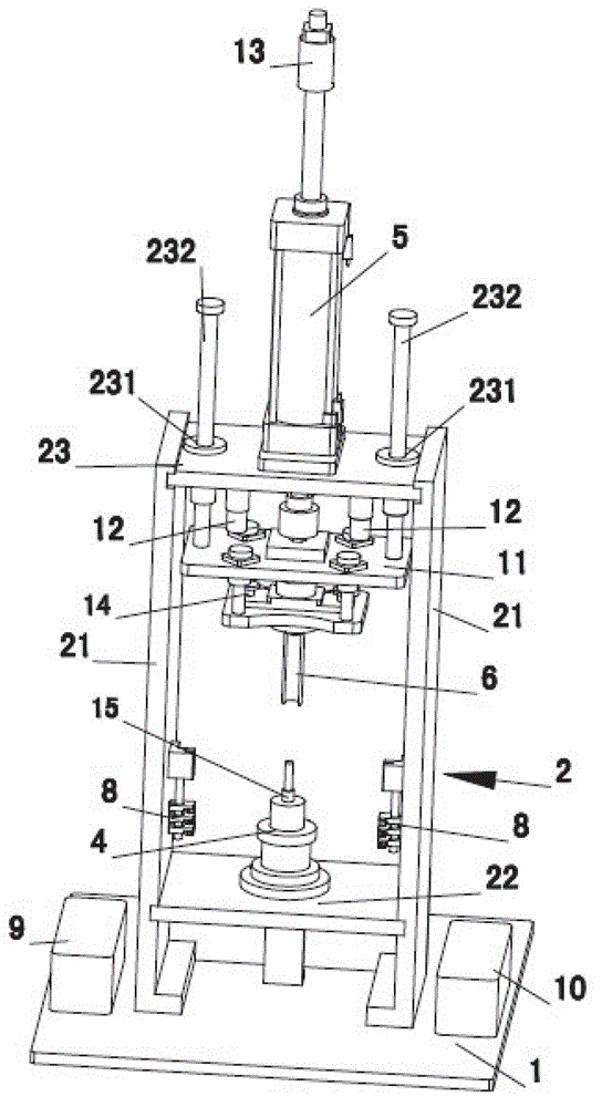
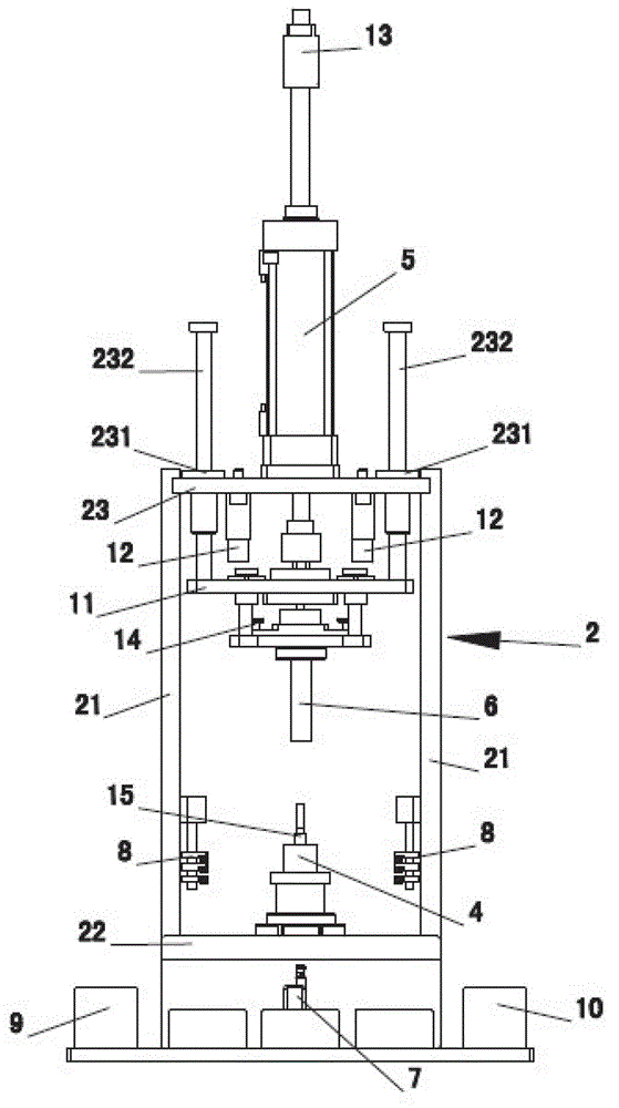
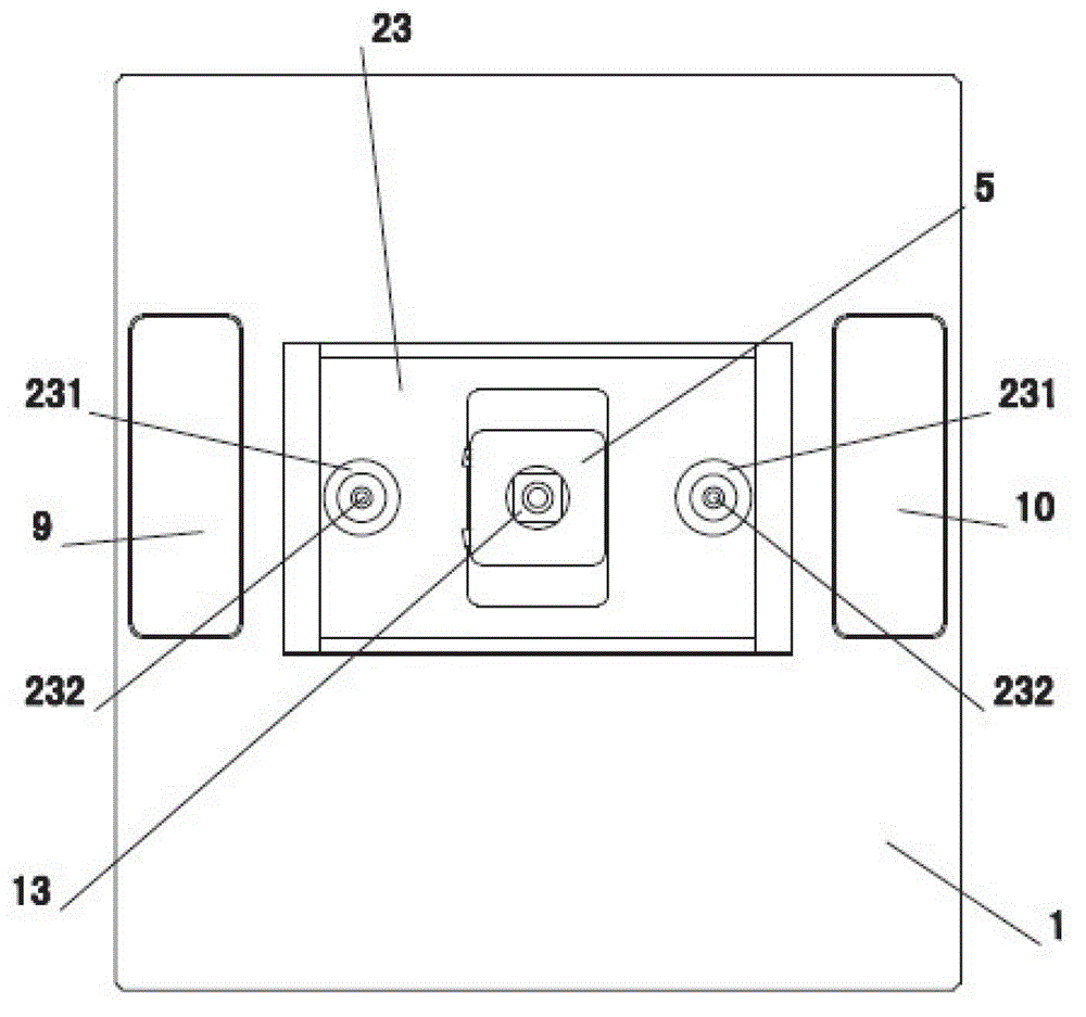
[0023] like Figure 1~3 Shown, a rotor iron core and magnetic ring bond strength detection device, including worktable 1, frame 2, workpiece placement 4 and detection mechanism; the frame 2 is arranged on the workbench 1, the frame 2 It is mainly composed of a column 21, a bottom plate 22 and a top plate 23, the bottom plate 22 is suspended in the lower part of the column 21; the bottom plate 22 is provided with a workpiece placement position 4; the detection mechanism is arranged on the top plate 23;

[0024] Described detection mechanism comprises pressing down cylinder 5, depression rod 6 and displacement sensor 7; Described depression rod 6 is vertically arranged on the below of described top board 23, and described down pressing cylinder 5 is fixedly arranged on top board 23, and its action end Act on the pressure rod 6, and drive the pressure rod 6 to move downward; the displacement sensor 7 is arranged below the bottom plate 22 corresponding to the workpiece placement p...


PUM


Abstract

The invention provides a detection device of bonding strength between a rotor core and a magnet ring, wherein the detection device can accurately reflect the bonding strength between the rotor core and the magnet ring. The detection device comprises an operating table-board, a machine frame, a workpiece placing position and a detection mechanism; the machine frame is placed on an operating platform and mainly comprises a stand column, a bottom plate and a top plate; the bottom plate is arranged on the lower portion of the stand column in a suspended mode and provided with the workpiece placing position; the detection mechanism is arranged on the top plate and comprises a downward pressing cylinder, a compression bar and a displacement sensor; the compression bar is vertically arranged below the top plate; the downward pressing cylinder is fixedly arranged on the top plate; the action end of the downward pressing cylinder acts on the compression bar and drives the compression bar to move downward; the displacement sensor corresponds to the workpiece placing position and is arranged below the bottom plate; and the compression bar, the workpiece placing position and the displacement sensor are coaxially arranged.

Description

technical field [0001] The invention relates to a detection device for the bonding strength of a rotor iron core and a magnetic ring. Background technique [0002] The motor part of the car seat motor is generally composed of a motor stator and a motor rotor, and a magnetic ring is installed on the motor rotor. When assembling the magnetic ring and the rotor, glue is usually coated on the outer peripheral surface of the rotor iron core, and then the magnetic ring is placed on the iron core, and the iron core and the magnetic ring are fixed by glue coating. The performance and quality of the rotor are closely related to whether the rotor is qualified in each process during the assembly process. Whether the bonding strength between the rotor core and the magnetic ring reaches the standard is an important indicator affecting the quality of the rotor. At present, there is no suitable detection instrument to detect the bonding strength between the rotor core and the magnetic ri...

Claims


Application Information

Patent Timeline
Patent Type & Authority Applications(China)
IPC IPC(8): G01N19/04
Inventor 张道德
Owner SUZHOU LING AUTOMATION EQUIP
Learn More