
Precise length matching method in optical fiber interference optical paths

An optical fiber interference and interference light technology, which is used in the coupling of optical waveguides and the use of optical devices to transmit sensing components. The effect of improving noise ratio and sensitivity and reducing influence

Inactive Publication Date: 2013-03-20
ZHEJIANG UNIV
View PDF8 Cites 6 Cited by
  • Summary
  • Abstract
  • Description
  • Claims
  • Application Information

AI Technical Summary

Problems solved by technology

At present, there is no method to accurately match the optical paths of the two optical paths. Only narrow linewidth lasers can be used as the system light source. The noise is large and the system is unstable, which greatly restricts the application of this optical fiber interference system.

Method used


Image

  • Precise length matching method in optical fiber interference optical paths
  • Precise length matching method in optical fiber interference optical paths
  • Precise length matching method in optical fiber interference optical paths

Examples

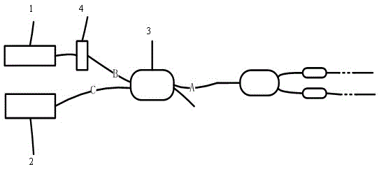

Embodiment Construction

[0025] The present invention will be further described below in conjunction with the accompanying drawings.

[0026] The optical path difference of the two arms of the Michelson or M-Z interference optical path must meet the requirements of the spectral width of the light source. Assuming the spectral width of the light source is Δλ, the maximum optical path difference Δ of the first arm optical path and the second arm optical path is required to be λ 2 / Δλ.

[0027] Such as figure 1 As shown, in order to meet the above requirements, the present invention adopts a method to find the optical path difference between the two arms of interference. Connect the input end of the Michelson-type interference optical path to the output end A of the coupler 3, the output end of the Michelson-type interference path is the first arm optical path and the second arm optical path, and connect one end of the filter 4 with different spectral widths to the wide-spectrum light source 1 , the ot...


PUM


Abstract

The invention discloses a precise length matching method in optical fiber interference optical paths. The method is suitable for a Michelson type interference optical path and an M-Z type interference optical path. The Michelson type interference optical path or the M-Z type interference optical path is connected with light sources with filters with different spectral widths, interference fringes are observed through a charge coupled device (CCD), preliminary judgment is carried out, differences of optical lengths of the two optical paths are reduced, the interference contrast ratios of the two optical paths are detected through a photoelectric detector, by means of comparison of the contrast ratios, the relative length of the optical lengths of the two optical paths is precisely judged, and the optical lengths of the two optical paths are matched in the method of abrading the tail ends of optical fibers of the optical paths. According to the method, the two optical paths are precisely matched with each other in a micron-sized mode, the spectral widths of usable light sources in the interference optical paths are widened, phase noise of the light sources and influences of the noise in the optical paths on the whole interference system are reduced, and the signal-to-noise ration and sensitivity of an interference-type optical sensing system are significantly improved.

Description

technical field [0001] The invention relates to an optical path matching method, in particular to a method for precisely matching the lengths of two arms in an optical fiber interference optical path. technical background [0002] With the continuous development of optical fiber technology, more and more sensors, such as hydrophones, accelerometers, pressure, temperature sensors, etc., use optical fiber interference systems, which need to detect the interference of two beams of light by changing the phase in the optical fiber. To judge the measurement, the two interference light paths of the sensitive part are required to be matched precisely. At present, there is no method to accurately match the optical paths of the two optical paths, and only narrow linewidth lasers can be used as the system light source. The noise is large and the system is unstable, which greatly restricts the application of this optical fiber interference system. Contents of the invention [0003] I...

Claims


Application Information

Patent Timeline
IPC IPC(8): G01D5/26G02B6/25
Inventor 王冬云王明超舒晓武刘承
Owner ZHEJIANG UNIV
Learn More