
Packaging container conveying device

A packaging container and conveying device technology, which is applied to conveyors, conveyor objects, transportation and packaging, etc., can solve the problems of sagging and swinging of the endless conveyor chain, poor stability of the conveying device, affecting the conveying of packaging containers, etc. The effect of improving the drying effect

Inactive Publication Date: 2013-03-20
SHANTOU XINQING CANNERY MACHINERY
View PDF9 Cites 11 Cited by
  • Summary
  • Abstract
  • Description
  • Claims
  • Application Information

AI Technical Summary

Problems solved by technology

[0004] Although the existing packaging container conveying device can convey the packaging container forward, the existing packaging container conveying device only has the function of conveying the packaging container, and does not have the function of making the packaging container realize its own rotation during the conveying process. In the drying process of metal cans, especially in the electromagnetic drying process of metal cans, the packaging container is required to be able to rotate while being conveyed forward with the endless conveyor chain, so that the packaging container can be heated evenly, thereby improving the drying efficiency of the packaging container. Drying effect, therefore, the existing packaging container conveying device can no longer meet the needs of packaging container drying
[0005] In addition, since the endless conveyor chain is only tensioned and straightened by the driving sprocket and the driven sprocket, the endless conveyor chain is prone to sag during operation under the action of gravity on the endless conveyor chain itself and the gravity on the packaging container. and swing, therefore, the stability of the existing packaging container conveying device is poor, which easily affects the conveying of the packaging container

Method used


Image

  • Packaging container conveying device
  • Packaging container conveying device

Examples


Embodiment Construction

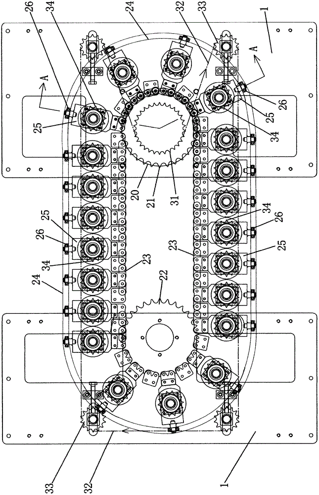
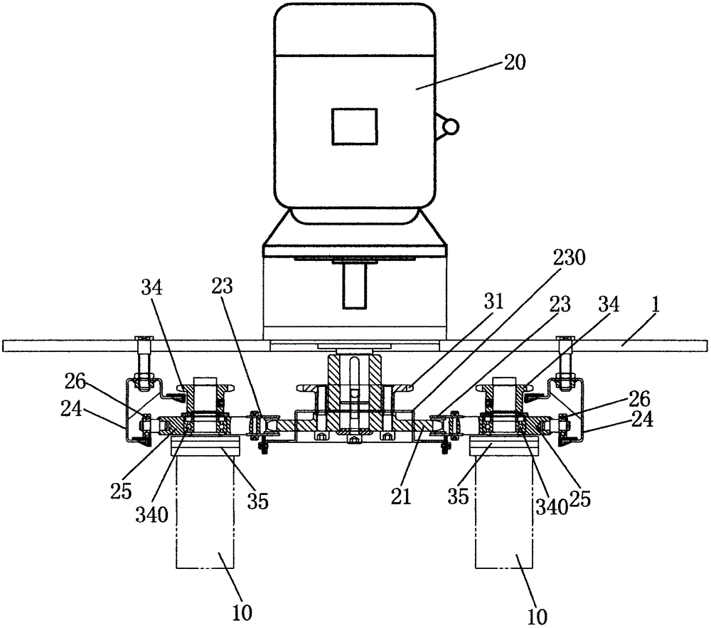
[0046] Such as figure 1 , figure 2As shown, the packaging container conveying device in this preferred embodiment includes a frame 1, a packaging container revolution conveying mechanism and a packaging container rotation mechanism, and the above packaging container revolution conveying mechanism includes a motor 20, a revolution driving sprocket 21, a revolution driven chain Wheel 22, revolution chain 23, revolution track 24, a plurality of rotation sprocket installation mechanisms, above-mentioned rotation sprocket installation mechanism comprises rotation sprocket installation plate 25 and roller 26; Above-mentioned packaging container rotation mechanism comprises rotation driving sprocket 31, rotation chain 32. A plurality of tensioning wheels 33 and a plurality of packaging container rotation adsorption components, the packaging container rotation adsorption assembly includes a rotation sprocket 34 and a packaging container adsorption piece 35;

[0047] Above-mentioned ...


PUM


Abstract

The invention discloses a packaging container conveying device, which is characterized by comprising a rack, a packaging container revolution conveying mechanism and a packaging container rotation mechanism, wherein the packaging container revolution conveying mechanism is arranged on the rack; the packaging container rotation mechanism is arranged on the packaging container revolution conveying mechanism and is in transmission connection with the packaging container revolution conveying mechanism. When the packaging container revolution conveying mechanism operates, the packaging container rotation mechanism revolves along with the packaging container revolution conveying mechanism, and meanwhile, the packaging container rotation mechanism rotates under the driving of the packaging container revolution conveying mechanism, so that the packaging container conveying device realizes that a packaging container can rotate during revolution to be uniformly heated, the drying effect of the packaging container is improved, the requirement of drying of the packaging container is met, and particularly the requirement of electromagnetic drying of a metal can is met.

Description

technical field [0001] The present invention relates to a conveying device, more particularly, to a packing container conveying device. Background technique [0002] At present, the packaging container conveying devices on the market generally include a frame, a motor, a driving sprocket, a driven sprocket, an endless conveying chain and a plurality of packaging container adsorption parts. The above-mentioned motor is fixedly installed on the frame, and the above-mentioned driving sprocket Coaxially installed on the power output shaft of the motor, the above-mentioned driven sprocket is rotatably installed on the frame, the above-mentioned endless conveyor chain is sleeved on the driving sprocket and the driven sprocket, and the above-mentioned motor passes through the driving sprocket and the driven sprocket The moving sprocket is in transmission connection with the endless conveying chain; the above-mentioned packing container absorbing part is fixedly installed on the end...

Claims


Application Information

Patent Timeline
Patent Type & Authority Applications(China)
IPC IPC(8): B65G17/12B65G47/244F26B25/00
Inventor 黄镇明杨伟文陈万伟卢家伟
Owner SHANTOU XINQING CANNERY MACHINERY
Learn More